Patent application title: Locking System for a Piece of Jewellery
Inventors:
Else Birgitte Stengaard Jepsen (Ringkoebing, DK)
IPC8 Class: AA44C518FI
USPC Class:
24265EC
Class name: Buckles, buttons, clasps, etc. strap-end-attaching devices end clasp
Publication date: 2008-11-06
Patent application number: 20080271296
Inventors list |
Agents list |
Assignees list |
List by place |
Classification tree browser |
Top 100 Inventors |
Top 100 Agents |
Top 100 Assignees |
Usenet FAQ Index |
Documents |
Other FAQs |
Patent application title: Locking System for a Piece of Jewellery
Inventors:
Else Birgitte Stengaard Jepsen
Agents:
ANTONELLI, TERRY, STOUT & KRAUS, LLP
Assignees:
Origin: ARLINGTON, VA US
IPC8 Class: AA44C518FI
USPC Class:
24265EC
Abstract:
A locking system (2) for a piece of jewelry, including mutually
complementary interacting locking parts (4, 6) shaped as coupling parts
of a male and female type, where each locking part (4, 6) additionally
includes polarized magnets (10, 12), where each locking part (4, 6)
opposite the coupling parts additionally includes end parts (8) with
connecting means (9) for connecting the end parts (8) with one or more
pieces of jewelry, e.g. in the form of necklaces, bracelets, ankle bands,
headbands, belts or the like.Claims:
1-10. (canceled)
11. A locking system for jewelry, comprising mutually complementary interacting locking parts shaped as a male and female type, with each of the locking parts including polarized magnets, wherein each locking part is opposite coupling parts and additionally includes end parts with means for connecting the end parts with one or more pieces of jewelry.
12. A locking system according to claim 11, comprising at least one intermediate piece which includes at least one additional coupling part for connecting with either one of the coupling parts or with a locking part of an attachment.
13. A locking system according to claim 12, comprising a tubular intermediate piece for enclosing one of the at least one intermediate piece with a radial eyelet for connecting with the attachment.
14. A locking system according to claim 11, wherein the end parts at a side facing the coupling parts include a connecting flange for engaging the end parts by screw threads in the end parts.
15. A locking system according to claim 11, wherein the end parts at a side facing the coupling parts include a connecting flange for engaging the end parts by glued faces in the end parts.
16. A locking system according to claim 11, wherein the end parts at a side facing away from the coupling parts include a central hole for receiving end parts of at least one piece of jewelry.
17. A locking system according to claim 11, wherein the loose end parts at a side facing away from the coupling parts include a projecting collar or flange for receiving end parts of at least one piece of jewelry.
18. A locking system according to claim 11, wherein the loose end parts at a side facing away from the coupling parts include a centrally projecting tube for receiving end parts of at least one piece of jewelry.
19. A locking system according to claim 11, comprising separate parts of jewelry with coupling parts of a male and female type for connection with at least one piece of jewelry.
20. A locking system according to claim 11, wherein separate parts of jewelry with mutually hingedly connected spatial parts include a cylindrical hollow for receiving the coupling parts of a male and female type with opposing ends for connection with one or more pieces of jewelry.
21. A locking system, comprising mutually complementary interacting locking parts shaped as a male and female type, with each of the locking parts including polarized magnets, wherein each locking part is opposite coupling parts and additionally includes end parts with means for connecting the end parts with at least one attachment.
22. A locking system according to claim 21, comprising at least one intermediate piece which includes at least one additional coupling part for connecting with either one of the coupling parts or with a locking part of that at least one attachment.
23. A locking system according to claim 22, comprising a tubular intermediate piece for enclosing one of the at least one intermediate piece with a radial eyelet for connecting with the at least one attachment.
24. A locking system according to claim 21, wherein the end parts at a side facing the coupling parts include a connecting flange for engaging the end parts by screw threads in the end parts.
25. A locking system according to claim 21, wherein the end parts at a side facing the coupling parts include a connecting flange for engaging the end parts by glued faces in the end parts.
26. A locking system according to claim 21, wherein the end parts at a side facing away from the coupling parts include a central hole for receiving end parts of at least one attachment.
27. A locking system according to claim 21, wherein the loose end parts at a side facing away from the coupling parts include a projecting collar or flange for receiving end parts of at least one attachment.
28. A locking system according to claim 21, wherein the loose end parts at a side facing away from the coupling parts include a centrally projecting tube for receiving end parts of at least one attachment.
Description:
BACKGROUND OF THE INVENTION
[0001]1. Field of the Invention
[0002]The present invention concerns a locking system for a piece of jewelry.
[0003]2. Description of the Prior Art
[0004]Locks for jewelry of the above type are usually designed as a combination of a chain end and a jewelry lock used as a termination or lock for jewelry, respectively, for one or more parallel necklaces, bracelets, ankle bands, headbands, belts or corresponding items, as ends of the chain or chains are fastened to the lock which has two parts, each containing a magnet so that the two parts may be held together (locked).
[0005]U.S. Pat. No. 6,640,398 describes a jewelry lock for securing opposing ends of chains and other pieces of jewelry. Each locking part contains an arrangement for securing separate locking parts by means of magnets arranged so that their poles attract each other. In a first embodiment, disc-shaped magnets are used which are inserted into slots of complementary interacting elongated bodies. In a second embodiment, disc-shaped magnets are disposed at opposite ends of mutually interacting locking parts, which are also designed with a bayonet locking mechanism. Common to the two embodiments is that connecting parts for the chains are constituted by permanent eyelets at the ends of respective locking parts.
SUMMARY OF THE INVENTION
[0006]The invention provides an improved locking system for jewelry of the above mentioned type, which by means of simple technical means improves the function of the locking system and provides the possibility of completely new applications.
[0007]The locking system according to the invention has each locking part opposite the coupling parts which additionally include loose end parts which are designed with connecting means adapted for connecting the end parts with one or more pieces of jewelry, for example, in the form of necklaces, bracelets, ankle bands, headbands, belts or the like. A new locking system is hereby provided by means of simple technical means, with improved function and enabling completely new applications.
[0008]The locking system according to the invention may suitably be formed so that it further includes one or more intermediate pieces that include interacting locking parts in the form of coupling parts for connecting with either the first-mentioned coupling parts or with locking parts of attachments, other jewelry or the like.
[0009]In order to enable use of the locking system according to the invention for separate parts of jewelry, it may advantageously be designed so that it includes a tubular intermediate piece which encloses one of the intermediate pieces, and which is designed with a radial eyelet for connecting with an attachment or similar part of jewelry.
[0010]In a preferred embodiment, the locking system according to the invention has the loose end parts at the side facing the coupling parts so that a connecting flange engages end parts of the coupling parts by means of interacting screw threads formed in respective parts.
[0011]Alternatively, the locking system according to the invention may be has the loose end parts at the side facing the coupling parts so that a connecting flange engages end parts of the coupling parts by means of interacting glued faces formed in respective parts.
[0012]In a preferred embodiment, the locking system according to the invention has the loose end parts at the side facing away from the coupling parts so that a central hole receives end parts of one or more pieces of jewelry, for example, in the form of necklaces, bracelets, ankle bands, headbands, belts or the like.
[0013]Alternatively, the locking system according to the invention has the loose end parts at the side facing away from the coupling parts so that a projecting collar or flange receives end parts of one or more pieces of jewelry, for example, in the form of necklaces, bracelets, ankle bands, headbands, belts or the like.
[0014]Or the locking system according to the invention has the loose end parts at the side facing away from the coupling parts so that a centrally projecting tube receives end parts of one or more pieces of jewelry, for example, in the form of necklaces, bracelets, ankle bands, headbands, belts or the like.
[0015]In a particular embodiment, the locking system according to the invention includes separate parts of jewelry provided with locking parts in the form of coupling parts of the male and female type, and which are for connection with one or more pieces of jewelry in the form of attachments, necklaces, bracelets, ankle bands, headbands, belts or the like.
[0016]The locking system according to the invention may in yet another embodiment include separate parts of jewelry in the shape of mutually hingedly connected spatial parts of jewelry with a mainly cylindric hollow for receiving the first-mentioned coupling parts of the male and female type, preferably not in assembled state, and which at opposing ends are from connection with one or more pieces of jewelry, for example, in the form of necklaces, bracelets, ankle bands, headbands, belts or the like.
BRIEF DESCRIPTION OF THE DRAWINGS
[0017]The invention is now explained more closely in connection with the drawing, in which:
[0018]FIG. 1 shows a side view of an embodiment of a locking system according to the invention;
[0019]FIG. 2 shows a sectional view along the section line A-A in FIG. 1;
[0020]FIG. 3 shows a perspective, exploded view of the locking system shown in FIG. 1;
[0021]FIG. 4 shows a side view of a locking part of the female type for the locking system shown in FIG. 1;
[0022]FIG. 5 shows a sectional view along the section line A-A in FIG. 4;
[0023]FIG. 6 shows a perspective, exploded view of the locking part shown in FIG. 4;
[0024]FIG. 7 shows a side view of a locking part of the male type for the locking system shown in FIG. 1;
[0025]FIG. 8 shows a sectional view along the section line A-A in FIG. 7;
[0026]FIG. 9 shows a perspective, exploded view of the locking part shown in FIG. 7;
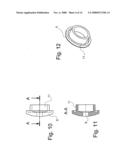
[0027]FIG. 10 shows a side view of a loose end part for a locking part;
[0028]FIG. 11 shows a sectional view along the section line A-A in FIG. 10;
[0029]FIG. 12 shows a perspective view of the end part shown in FIG. 10;
[0030]FIG. 13 shows a side view of a second embodiment of a locking system according to the invention;
[0031]FIG. 14 shows a sectional view along the section line A-A in FIG. 13;
[0032]FIG. 15 shows a perspective, exploded view of the locking system shown in FIG. 13;
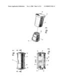
[0033]FIG. 16 shows a side view of a locking part of the female type for the locking system shown in FIG. 13;
[0034]FIG. 17 shows a side view, partly in section along the section line A-A in FIG. 16;
[0035]FIG. 18 shows a perspective view, partly sectional, of the locking part shown in FIG. 17;
[0036]FIG. 19 shows a side view of a locking part of the male type for the locking system shown in FIG. 13;
[0037]FIG. 20 shows a side view, partly in section along the section line A-A in FIG. 19;
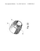
[0038]FIG. 21 shows a perspective view, partly sectional, of the locking part shown in FIG. 20;
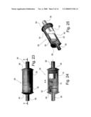
[0039]FIG. 22 shows a perspective view of the locking part shown in FIG. 19;
[0040]FIG. 23 shows a side view of another embodiment of a locking system according to the invention;
[0041]FIG. 24 shows a side view, partly in section along the section line A-A in FIG. 23;
[0042]FIG. 25 shows a perspective view, partly in section, of the locking system shown in FIG. 24;
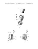
[0043]FIG. 26 shows a perspective, exploded view another embodiment of a locking system according to the invention;
[0044]FIG. 27 shows a perspective view of yet an embodiment of a locking system according to the invention;
[0045]FIG. 28 shows a perspective view of yet an embodiment of a locking system according to the invention;
[0046]FIG. 29 shows a perspective view of a modified embodiment of a locking system according to the invention; and
[0047]FIG. 30 shows a perspective view of another embodiment of a locking system according to the invention.
DETAILED DESCRIPTION OF THE INVENTION
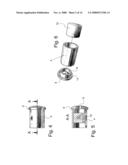
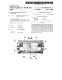
[0048]The locking system 2 shown in FIGS. 1-3 has of a locking part 4 of the female type and a locking part 6 of the male type, which locking parts 4 and 6 each includes end parts 8, respectively, with connecting holes 9 that provide the ability for passing through of a cord for a piece of jewelry, or example a string of pearls. The locking parts 4 and 6 are internally fitted with magnets 10 and 12 polarized so that they attract each other when the locking parts 4 and 6 are joined, as shown in FIGS. 1 and 2. The end parts 8 and the locking parts 4 and 6 may be designed with complementary screw threads or glued faces 11.
[0049]In FIG. 2 is shown with dotted lines that the locking system 2 may include a tubular part 14 which is for disposition between the end parts 8 externally of the locking parts 4 and 6, and which has a radial connecting eyelet 16. In FIGS. 4-12, respective parts are designated with the same reference number as in FIGS. 1-3.
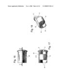
[0050]The locking system 18 shown in FIGS. 13-15 is constructed in principle entirely corresponding to the above described locking system 2, as the locking system 18 has a locking part 20 of the female type and a locking part 22 of the male type. Both locking parts 20 and 22 are provided with loose end parts 8 with connecting holes 9 serving for passing through of a cord of a piece of jewelry, for example, a string of pearls. Both locking parts 20 and 22 have internal holding magnets 10, 12.
[0051]Furthermore, the locking part 20 is provided with or designed with supplementing internal locking pins 24 which are disposed diametrically opposite each other, and which are adapted to interact with external locking grooves 26 formed in the locking part 22, so that the locking parts 20 and 22 may be interlocked by mutual rotation. In FIGS. 16-22, respective parts are designated with the same reference number as in FIGS. 13-15.
[0052]The locking system 28 in FIGS. 23-25 has a locking part 30 of the female type and a locking part 32 of the male type. Each of the locking parts 30 and 32 are connected by screw threads with loose end parts 36 with a centrally projecting tubular connecting part 38. Each of these are intended for externally receiving a part of jewelry, for example, a first pearl of a pearl string, the carrier cord of which runs through the tubular connecting part 38 into locking parts 30 and 32 and is fastened in end parts 36 by means of suitable fastening means, for example, glue or knots or a combination thereof. The locking parts 30 and 32 are provided with internal holding magnets 10, 12 and with supplementing locking means in the form of an external locking pin 40 on the locking part 32 and a complementary internal locking groove 42 on the locking part 30.
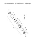
[0053]The locking system 44 shown in FIG. 26 has a locking part 46 of the female type and a locking part 48 of the male type. The locking parts 46 and 48 are for example made of noble metal, for example gold or silver, why the locking parts 46, 48 are provided with inserts 50 and 52, of which the insert 50 is made of stainless steel with a locking groove 54 and a locking position with a locking hole 56, respectively, in which the insert 56 of stainless steel may engage with an external locking pin 58. The locking parts 46 and 48 furthermore have internal holding magnets 10 and 12 disposed in the inserts 50 and 52. Besides, the locking parts 50 and 52 have loose end parts 60 with relatively large connecting holes 62 for leather straps, of which loose ends may be fastened in the end parts 60 by means of locking pins inserted through transverse holes 64 of the end parts 60.
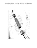
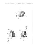
[0054]FIG. 27 shows a locking system 62 which, besides a locking part 64 of the female type and a locking part 66 of the male type, comprises an intermediate piece 68 which at opposite ends is provided with complementing locking parts so that the intermediate piece 68 may be fixed in a secure way between the locking parts 64 and 66. The intermediate piece 68 may, for example, be used to connect a separate part of jewelry to one or more pieces of jewelry, for example, in the form of necklaces, bracelets, ankle bands, headbands, belts or the like. As indicated, the intermediate piece 68 may possibly have several lesser intermediate pieces so that the length may be adjusted thereby.
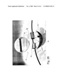
[0055]FIG. 28 shows a locking system 70 where a spatial jewelry part 72 having two hingedly connected halves 74 in which is formed a mainly cylindric hollow 76 adapted for receiving a locking part 78 of the female type and a locking part 80 of the male type in such a way that the locking parts 78 and 80 may be fixed in the hollow 76 when the halves 74 are joined together. The jewelry part 72 is a magnetic material so that the holding magnets in the locking parts 78 and 80 also can hold the jewelry part 72 closed around the locking parts 78 and 80. If the jewelry part 72 is made of non-magnetic material, there may--as shown in FIG. 29--be provided an external lock 82 for holding the jewelry part 72 closed around the locking parts 78 and 80.
[0056]The locking system 84 shown in FIG. 30 includes a larger jewelry part 86 which at one side is fitted with a locking part 88 of the male type that interacts with a locking part 90 of the female type which is mounted at the end of a jewelry cord 92, which at the opposite end is provided with a locking part 94 of the male type interacting with a locking part 96 of the female type which is fitted in the jewelry part 86 diametrically opposite the locking part 88.
User Contributions:
comments("1"); ?> comment_form("1"); ?>Inventors list |
Agents list |
Assignees list |
List by place |
Classification tree browser |
Top 100 Inventors |
Top 100 Agents |
Top 100 Assignees |
Usenet FAQ Index |
Documents |
Other FAQs |
User Contributions:
Comment about this patent or add new information about this topic:
Images included with this patent application:
 |  |
 |  |
 |  |
 |  |
 |  |
 |  |
| Similar patent applications: | |
| Date | Title |
|---|---|
| 2009-03-26 | Stay system for pant legs |
| 2013-06-13 | Clasp for a watch bracelet or a belt |
| 2013-06-27 | Clamping members and clamping devices |
| 2013-06-27 | Slider for slide fastener |
| 2013-07-11 | Slider for slide fastener |
| New patent applications in this class: | |
| Date | Title |
|---|---|
| 2014-10-09 | Strap attachment system for orthopedic device |
| 2013-12-26 | Latching devices for bracelets and/or animals' collars and chains |
| 2012-09-27 | Extensible clasp for a bracelet, in particular a watchstrap |
| 2012-09-27 | Bracelet clasp |
| 2012-09-27 | Bracelet clasp |
| Top Inventors for class "Buckles, buttons, clasps, etc." | |
| Rank | Inventor's name |
|---|---|
| 1 | Keiichi Keyaki |
| 2 | Andreas Hörtnagl |
| 3 | Toshio Iwahara |
| 4 | Joachim Fiedler |
| 5 | Allison S. Conner |