Patent application title: Means for Fire Protection of Pipe Joints and Valves in Pipelines
Inventors:
Magne Stenseide (Kjerrgarden, NO)
IPC8 Class: AF16L5916FI
USPC Class:
285 54
Class name: Insulated between serially connected parts socket
Publication date: 2008-10-23
Patent application number: 20080258458
Inventors list |
Agents list |
Assignees list |
List by place |
Classification tree browser |
Top 100 Inventors |
Top 100 Agents |
Top 100 Assignees |
Usenet FAQ Index |
Documents |
Other FAQs |
Patent application title: Means for Fire Protection of Pipe Joints and Valves in Pipelines
Inventors:
Magne Stenseide
Agents:
Ronald R. Santucci;Frommer Lawrence & Haug
Assignees:
Origin: NEW YORK, NY US
IPC8 Class: AF16L5916FI
USPC Class:
285 54
Abstract:
Means for fire protection of pipe joints and valves in a pipeline,
comprising two socket halves being situated tightly against each other
and against the pipe line and surrounding the joint, valve or such, where
the socket halves being made by a perforated plate (6) in stainless
steel, by fire isolation (7, 8) of heat expanding epoxy material on the
inside, on the outside or on both sides, and that one of the edges of the
socket halves being situated against each other having an internal cover
plate (9) with fire isolation (8) which covers the joint between the two
halves and prevent penetration of hot gasses into the internal of the
socket halves.Claims:
1-3. (canceled)
4. Means for fire protection of pipe joints and valves in a pipeline, comprising two socket halves being situated tightly against each other and against the pipe line and surrounding the joint, valve or such, wherein the socket halves being made by a perforated plate in stainless steel, by fire isolation of heat expanding epoxy material on the inside, on the outside or on both sides, and that one of the edges of the socket halves being situated against each other having an internal cover plate with fire isolation which covers the joint between the two halves and prevent penetration of hot gasses into the internal of the socket halves.
5. Means according to claim 4, wherein the inner perforated plate of the socket halves having a bent-angle (braking edge) near the edges of the socket halves being situated towards each other.
6. Means according to claim 4, wherein a heat swelling gasket being arranged between the edge of the socket halves being situated against the outer isolation of the pipes and the fire isolation.
7. Means according to claim 5, wherein a heat swelling gasket being arranged between the edge of the socket halves being situated against the outer isolation of the pipes and the fire isolation.
Description:
[0001]The present invention is related to a means for fire protection of
pipe joints and valves in pipelines.
[0002]In case of a fire on or at valves in pipelines or pipe joints it is important that these joints are secured in the best possible way and additionally maintains their function as long as possible during a fire. The pipe joints may be flash connection which by testing of their fire protections should provide documentation for resistance against fire loads such as jet fires and hydrocarbon fires.
[0003]With the means for fire protection according to the present invention as defined by the features stated in the claims, the above mentioned objectives are secured.
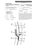
[0004]The drawing discloses in FIG. 1 a longitudinal section through a pipe joint with is the means for fire protection according to the invention,
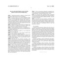
[0005]FIG. 2 discloses in detail in a cross section the connection to the pipe and
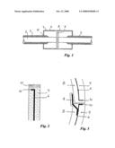
[0006]FIG. 3 discloses in a cross section a detail of the means for fire protection comprising a joint.
[0007]FIG. 1 discloses a flange coupling of two pipes 1 and 2 being connected in a steel case 5. The connection may comprise a valve, flanges or such. Around the pipes 1 and 2 is arranged isolation 3 and 4.
[0008]The means for fire protection according to the present invention comprises to sleeve halves with a perforated stainless steel plate 6 covered by fire isolation 7 and 8 in the shape of heat expanding epoxy products. The fire isolation 7 and 8 may be applied on both sides of the perforated steel plate 6, or only on one of the sides of the steel plate 6.
[0009]The two socket halves comprise end walls being pressed against the isolation 3 and 4 of the pipes 1 and 2 with a heat swelling gasket 11 as disclosed in FIG. 1. On the inside of one of the socket halves cover plates 9 are secured having fire isolation across the joints. In this way it is avoided that hot gasses penetrate into the inside or underside of the two gasket halves. The joints are enforced by a bent angle (braking edge) 10 on the steel plates 6.
[0010]The two socket halves thereafter are clamped, preferably with not disclosed clamping elements of the type over-a-centre-position, of the type suitcase-locks or such.
[0011]By using the heat expanding gaskets, perforated steel armouring and heat expanding epoxy coating in addition to the protection being made completely flexible, a safe fire protection is achieved.
[0012]The means for fire protection according to the present invention is especially developed for use on installation which are exposed or extreme climatic conditions, especially large temperature differences and high relative humidity. This is the case for installations both on land and installations offshore.
User Contributions:
comments("1"); ?> comment_form("1"); ?>Inventors list |
Agents list |
Assignees list |
List by place |
Classification tree browser |
Top 100 Inventors |
Top 100 Agents |
Top 100 Assignees |
Usenet FAQ Index |
Documents |
Other FAQs |
User Contributions:
Comment about this patent or add new information about this topic:
Images included with this patent application:
 |  |
 |
| Similar patent applications: | |
| Date | Title |
|---|---|
| 2012-04-26 | Apparatus for connecting and sealing pipelines |
| 2012-09-20 | Assembly for producing a threaded connection, method for making up and breaking out said connection and use of said connection in a work over riser |
| 2012-09-13 | Grooved pipe fitting apparatus and methods of using and manufacturing the same |
| 2010-12-23 | Socket for pipe joint and pipe joint |
| 2010-12-30 | Socket for pipe joint and pipe joint |
| New patent applications in this class: | |
| Date | Title |
|---|---|
| 2014-06-26 | Filler-neck coupling |
| 2013-12-05 | Connector |
| New patent applications from these inventors: | |
| Date | Title |
|---|---|
| 2013-12-12 | Fire protected steel structure and removable panels for fire protection of a steel structures |
| 2010-01-14 | Means for fire protection of pipes, pipe joints, flanges, valves, insulation and steel constructions |
| Top Inventors for class "Pipe joints or couplings" | |
| Rank | Inventor's name |
|---|---|
| 1 | Peter C. Williams |
| 2 | Douglas R. Dole |
| 3 | Mark A. Clason |
| 4 | Avi Chiproot |
| 5 | Alain-Christophe Tiberghien |