Patent application title: Flat heat pipe
Inventors:
Yaw-Huey Lai (Taipei County, TW)
Assignees:
TAI-SOL ELECTRONICS CO., LTD.
IPC8 Class: AF28D1504FI
USPC Class:
16510426
Class name: Liquid fluent heat exchange material utilizing change of state utilizing capillary attraction
Publication date: 2008-10-09
Patent application number: 20080245511
Inventors list |
Agents list |
Assignees list |
List by place |
Classification tree browser |
Top 100 Inventors |
Top 100 Agents |
Top 100 Assignees |
Usenet FAQ Index |
Documents |
Other FAQs |
Patent application title: Flat heat pipe
Inventors:
Yaw-Huey Lai
Agents:
BACON & THOMAS, PLLC
Assignees:
TAI-SOL ELECTRONICS CO., LTD.
Origin: ALEXANDRIA, VA US
IPC8 Class: AF28D1504FI
USPC Class:
16510426
Abstract:
A flat heat pipe including: a tubular member having two sealed ends, a
capillary wick being disposed at the internal sidewall of said tubular
member and a liquid contained in said tubular member. Said tubular member
defines a flat section and a thicker section at least. By the way, the
present invention can solve the problem of the accumulated water inside
the heat pipe of prior art and keeps a good efficiency of uniform
temperature, and the radiation efficiency is better then the heat pipe of
prior art.Claims:
1. A flat heat pipe including:a tubular member having two sealed ends;a
capillary wick being disposed at the internal sidewall of said tubular
member;a liquid contained in said tubular member;said tubular member
defining a heated section and a condensed section, andsaid tubular member
defining a flat section and a thicker section at least;said heated
section including a portion of said flat section at least, andsaid
condensed section including a portion of said thicker section at least.
2. The pipe as claimed in claim 1, wherein said capillary wick can be a mesh or copper powder or grooves that is provided at the internal sidewall of said tubular member.
3. The pipe as claimed in claim 1, wherein said tubular member makes of copper.
4. The pipe as claimed in claim 1, wherein said thicker section disposes at one end of said tubular member.
5. The pipe as claimed in claim 1, wherein said flat section disposes at one end of said tubular member.
6. The pipe as claimed in claim 1, wherein the caliber that surrounds by the capillary wick in said thicker section is bigger than the caliber that surrounds by the capillary wick in said flat section.
7. The pipe as claimed in claim 1, wherein said flat heat pipe provides a plurality of dissipating fins further more and said dissipating fins disposes on the surface of said tubular member near said thicker section.
8. The pipe as claimed in claim 1, wherein said thicker section locates at the rear end of said tubular member.
Description:
BACKGROUND OF THE INVENTION
[0001]1. Field of the Invention
[0002]The present invention relates to a heat-dissipating device and more particular to a flat heat pipe.
[0003]2. Description of the Related Art
[0004]A conventional heat pipe is usually composed of a sealed tubular member, a capillary wick mounted on the internal wall of the sealed tubular member, and adequate liquid, employing the liquid-vapor transformation and the flowage of the liquid for thermal conduction. In practical operation, water located at a heated section of the sealed tubular member is heated to be transformed into vapor, the vapor is then diffused to a condensed section of the sealed tubular member to be transformed into water, and then the water is returned to the heated section through the capillary action generated by the capillary wick, thus completing heat exchange. Such endless cycles of endothermic and exothermic reactions can effect rapid thermal conduction.
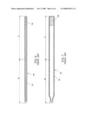
[0005]However, in some device with limited space such as notebooks, display cards or the other devices that will dissipate heat. At the time of assembling the heat pipe, said heat pipe need to press flat before it is assembled some time. The inside status of the heat pipe that is flattened and show in FIG. 6 and FIG. 7. The space inside the heat pipe 70 shrinks and causes the space for the vapor to move around small and thinness owing to the heat pipe is pressed flat. After the vapor is transformed into water 79 in the condensed section C, some of the water returns to the heated section H. But, most of the water 79 will stay in the condensed section C. This is owing to the space that is surrounded by capillary wick 73 shrinks and makes the structures similar to a capillary. Because of the capillarity, the water 79 will stay in the condensed section C and stores up.
[0006]The water in the condensed section C will store up since the water can't return to the heated section H all. The vapor can't do the liquid-vapor transformation in the condensed section C. That is to say, the heat can't transmit to this section. This status of accumulated water causes the temperature of the accumulated water portion dropping and breaks the status of a uniform temperature of the whole, and the effect of heat transmission drops too. This situation needs to improve.
SUMMARY OF THE INVENTION
[0007]The primary object of the present invention is to provide a flat heat pipe, which is able to solve the problem of accumulated water and provides a good character of uniform temperature.
[0008]To achieve this object of the present invention, the flat heat pipe including: a tubular member having two sealed ends, a capillary wick being disposed at the internal sidewall of said tubular member and a liquid being disposed in said tubular member. Said tubular member defines a flat section and a thicker section at least. Whereby the present invention can solve the problem of the accumulated water inside the heat pipe of the prior art and keeps a good efficiency of uniform temperature, and the radiation efficiency is better then the heat pipe of prior art.
BRIEF DESCRIPTION OF THE DRAWINGS
[0009]FIG. 1 is a sectional view of the present invention;
[0010]FIG. 2 is an enlarged view of a portion of the FIG. 1;
[0011]FIG. 3 is a sectional view of the present invention in practice;
[0012]FIG. 4 is another sectional view of the present invention in practice;
[0013]FIG. 5 is a sectional view of a heat pipe of prior art, which shows a side sectional view;
[0014]FIG. 6 is a sectional view of a heat pipe of prior art, which shows a vertical sectional view;
[0015]FIG. 7 is a sectional view of a heat pipe of prior art, which shows a top sectional view;
DETAILED DESCRIPTION OF THE INVENTION
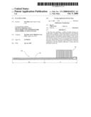
[0016]Referring to FIG. 1 and FIG. 2, the flat heat pipe 10 of present invention including: a tubular member 11, a capillary wick 21 and liquid 31. Wherein:
[0017]Said tubular member 11 makes of copper and both ends are sealed.
[0018]Said capillary wick 21 is disposed at the internal sidewall of said tubular member 11. Said capillary wick 21 can be a metal mesh or copper powder or grooves that is provided at the internal sidewall of said tubular member 11. In this embodiment, present invention takes the sintering by copper powder as an illustration. The metal mesh and the grooves type are all prior art skills and the capillary wick is not the technique key point of present invention, so there are no more redundancy words.
[0019]Said liquid 31 is disposed into said tubular member 11. Wherein said tubular member 11 defines a flat section 12 and a thicker section 14. Said flat section 12 is placed at one end of said tubular member 11 and said thicker section 14 is placed at the other end, namely the rearward end. The caliber that surrounds by the capillary wick 21 in said thicker section 14 is bigger than the caliber that surrounds by the capillary wick 21 in said flat section 12. Said tubular member 111 defines a heated section H and a condensed section C more over. Said heated section H overlaps a portion of said flat section C and connects with a heat-dispersing device (not shown). Said condensed section C includes said thicker section 14 and a portion of said flat section 12. In other words, said condensed section C is combined with said thicker section 14 and a portion of said flat section 12.
[0020]According to the structures as aforesaid in practical operation, said liquid 31 located in the heated section H is heated to be transformed into vapor, the vapor is then diffused to said condensed section C through the space that surrounds by said capillary wick 21. Said vapor is transformed into water in said condensed section C again and goes into said capillary wick 21. By the disposal of said thicker section of present invention, the caliber that surrounds by the capillary wick 21 in said thicker section 14 is bigger than the caliber that surrounds by the capillary wick 21 in said flat section 12. The quantity of said liquid 31 condensed in said capillary wick 21 is not enough to block the space surrounds by the capillary wick 21. FIG. 2 shows the status of said liquid 31 condensed in said capillary wick 31. So, said liquid 31 can return to said heated section H by said capillary wick 21 and keeps a good circulating efficiency, and then the efficiency of uniform temperature and the transmission effect will be good.
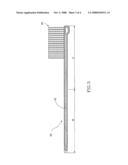
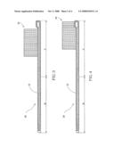
[0021]Referring to FIG. 3, Said flat heat pipe 10 provides a plurality of dissipating fins 41 further more. Said dissipating fins 41 are disposed on the surface of said condensed section C of said tubular member 11. That is to say, said dissipating fins 41 are near said thicker section 14. FIG. 4 and FIG. 5 show the other disposals of said dissipating fins 41. The main object of adding said dissipating fins 41 is for increasing the radiation efficiency of said heated section C.
[0022]There is an addition remark. On the tubular member 11 of present invention, the definitions of the location and the quantity of said flat section 12 and thicker section 14 can be different. For example, said tubular member could provide two thicker sections at both ends separately and a flat section in the middle. This is a change shape practice as aforesaid embodiment. This change shape practice is an equivalent change of the claims of present invention and it should be included in the scope of the claims.
[0023]In conclusion, the efficiencies of present invention are:
[0024]1. Solving the problems about the accumulated water and the poor efficiency of uniform temperature in the flat heat pipe of prior art.
[0025]By the design of the thicker section in present invention, the liquid can stay in the capillary wick of the condensed section without blocking the space that surrounds by the capillary wick. So, the problem of the accumulated water in the flat heat pipe of prior art can be solved and keeps a good efficiency of uniform temperature.
[0026]2. The radiation efficiency is better then prior art.
[0027]Due to the flat section and the thicker section are provided in present invention, the inside space is bigger than the heat pipe that is pressed flat in prior art. The quantity of the heat transmission and radiation efficiency is better than prior art as a whole. Besides, the quantity of the heat transmission is larger than the heat pipe as a whole because that the present invention solves the problem of the accumulated water in the flat heat pipe in prior art.
User Contributions:
comments("1"); ?> comment_form("1"); ?>Inventors list |
Agents list |
Assignees list |
List by place |
Classification tree browser |
Top 100 Inventors |
Top 100 Agents |
Top 100 Assignees |
Usenet FAQ Index |
Documents |
Other FAQs |
User Contributions:
Comment about this patent or add new information about this topic:
Images included with this patent application:
 |  |
 |  |
 |
| Similar patent applications: | |
| Date | Title |
|---|---|
| 2010-08-26 | Flat heat pipe |
| 2010-12-23 | Self-excited oscillating flow heat pipe |
| 2011-05-05 | Flat heat pipe with hook capillary tissue |
| 2011-07-21 | Flat heat pipe with vapor channel |
| 2011-07-21 | Flat heat pipe |
| New patent applications in this class: | |
| Date | Title |
|---|---|
| 2019-05-16 | Method for preparing porous wick and product prepared by the same |
| 2019-05-16 | Semiconductor device assembly with vapor chamber |
| 2019-05-16 | Straight-through structure of heat dissipation unit |
| 2018-01-25 | Diphasic cooling loop with satellite evaporators |
| 2017-08-17 | Heat pipe |
| New patent applications from these inventors: | |
| Date | Title |
|---|---|
| 2012-12-06 | Card connector with separable card tray |
| 2011-02-24 | Card connector capable of scraping |
| 2010-11-25 | Card connector capable of detecting card entry |
| 2010-05-13 | Card connector capable of detecting card insertion |
| 2009-04-23 | Card connector with terminal protection |
| Top Inventors for class "Heat exchange" | |
| Rank | Inventor's name |
|---|---|
| 1 | Levi A. Campbell |
| 2 | Chun-Chi Chen |
| 3 | Tai-Her Yang |
| 4 | Robert E. Simons |
| 5 | Richard C. Chu |