Patent application title: Garden shoe having breathing tubes
Inventors:
Russell J. Stark (Lake Oswego, OR, US)
IPC8 Class: AA43B300FI
USPC Class:
36113
Class name: Boots, shoes, and leggings boots and shoes occupational or athletic shoe (e.g., roof climbing, gardening, etc.)
Publication date: 2008-10-02
Patent application number: 20080235994
Inventors list |
Agents list |
Assignees list |
List by place |
Classification tree browser |
Top 100 Inventors |
Top 100 Agents |
Top 100 Assignees |
Usenet FAQ Index |
Documents |
Other FAQs |
Patent application title: Garden shoe having breathing tubes
Inventors:
Russell J. Stark
Agents:
CHERNOFF, VILHAUER, MCCLUNG & STENZEL
Assignees:
Origin: PORTLAND, OR US
IPC8 Class: AA43B300FI
USPC Class:
36113
Abstract:
A waterproof garden shoe has a plurality of passageways located in the
shoe upper. One or more tubes located on the upper are in fluid
communication with these passageways. The tubes have an opening which
allows ambient air to enter the tubes and pass into the shoes through the
passageways to cool the user's feet. The openings in each tube are
located below the passageways that communicate with that tube to prevent
water entering the tube from entering the shoe through the passageway.Claims:
1. A breathable garden shoe comprising:(a) an upper having an outer
surface and an inner surface;(b) a sole connected to said upper;(c) said
upper defining a plurality of passageways, which extend between said
inner and outer surfaces;(d) at least one tube located on said outer
surface, said tube being in fluid communication with at least one of said
passageways; and(e) said tube having at least one opening on the exterior
of said shoe, said opening being below the passageways the tube
communicates with.
2. The shoe of claim 1 wherein the opening in said tube is proximate where said sole is connected to said upper.
3. The shoe of claim 1 wherein said tube is integrally molded as part of said upper.
4. The shoe of claim 1 wherein said tube is attached to said outer surface.
5. The shoe of claim 1 wherein said upper and said tube are water impervious.
6. The shoe of claim 1 wherein said upper has opposed sides and each said tube is in communication only with passageways on one side of said upper.
7. The shoe of claim 1 wherein said upper has opposing sides and each said tube is in communication with passageways on both sides of said upper.
8. The shoe of claim 1 wherein said upper has opposed sides and a portion of said tubes are in communication with passageways on one side of said upper, and a portion of said tubes are in communication with passageways on both sides of said upper.
Description:
BACKGROUND OF THE INVENTION
[0001]Shoes specifically designed for working in the garden need to be waterproof. This often is accomplished by molding them as an integral unit from rubber or a soft plastic material which is impervious to water. However, shoes of this type do not breathe like leather or fabric shoes do so the user's feet get hot when the shoes are worn in warm weather. As a result, it has become common to provide ventilation openings in the shoes to allow ambient air to enter them and cool the wearer's feet. While placing ventilation openings in garden shoes prevents the wearer's feet from becoming too warm, it also essentially prevents the shoes from being waterproof regardless of the material they are made from. While many attempts have been made to prevent water from entering ventilation openings in shoes, they have been unsuccessful in doing so.
BRIEF SUMMARY OF THE INVENTION
[0002]The subject invention overcomes the shortcoming of the prior art ventilated garden shoes by providing tubes which are attached to the shoes' upper and communicate with the inside of the shoes through passageways located in the uppers. Each tube has an opening that is located lower on the shoe than any of the passageways connected to that tube.
[0003]The foregoing and other objectives, features, and advantages of the invention will be more readily understood upon consideration of the following detailed description of the invention, taken in conjunction with the accompanying drawings.
BRIEF DESCRIPTION OF THE SEVERAL VIEWS OF THE DRAWINGS
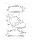
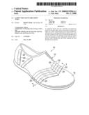
[0004]FIG. 1 is a perspective view showing a garden shoe embodying the subject invention.
[0005]FIG. 2 is a cross-sectional view taken on line 2-2 of FIG. 1.
[0006]FIG. 3 is a cross-sectional view similar to FIG. 2, showing another embodiment.
DETAILED DESCRIPTION OF PREFERRED EMBODIMENT
[0007]Referring now to FIG. 1 of the drawings, a garden shoe 10 has an upper 12 with an inner surface 14 and an outer surface 16, and a sole 18. Preferably the upper and sole are made from a rubber or plastic material that makes them impervious to water. The upper and sole can be molded as an integral unit or it can be separate elements which are joined together by conventional means.
[0008]Located in the upper 12 are a series of passageways 20 which extend between the inner and outer surfaces 14, 16. The passageways can be located almost anywhere on the upper and are shown in the drawings as being located near the toe portion of the shoe or near the heel end of the shoe. The passageways preferably are arranged in linear rows and are symmetrical on each side of the shoe. If the shoe is molded, the passageways can be molded as an integral part of the upper.
[0009]Located on the upper 12 are a plurality of hollow tubes 22. Each tube 22 is connected to at least one passageway 20 and preferably is connected to all of the passageways in a row. If the shoe is molded the tubes preferably are formed as part of the molding process. However, they can be attached later by thermal welding or by an adhesive. In any event the tubes 22 also preferably are made from a water impervious material, and typically are made from the same material as the upper.
[0010]In addition to opening into the passageways 20, the tubes have exterior openings 24 at one or both of their ends. The openings 24 in any tube are located below all of the passageways that tube is connected to. In the embodiment illustrated the openings 24 in all of the tubes are located around where the upper 16 and sole 18 connect. While this is the preferred location of the openings 24, they can be higher on the shoe if desired. The tubes can either be connected to passageways 20 on only one side of the shoe, FIG. 2, or on passageways on both sides of the shoe, FIG. 3. In the former situation the tubes have an opening at one end 26 only and the other end 28 is sealed. In the latter situation both ends 30 are open.
[0011]Having the openings 24 in every tube located below the passageway that tube is connected to ensures that no water can enter the tube and flow up to the passageway and enter the shoe. However, ambient air can flow up the tubes into the shoes through the passageways and cool the user's feet.
[0012]The terms and expressions which have been employed in the foregoing specification are used therein as terms of description and not of limitation, and there is no intention, in the use of such terms and expressions, of excluding equivalents of the features shown and described or portions thereof, it being recognized that the scope of the invention is defined and limited only by the claims which follow.
User Contributions:
comments("1"); ?> comment_form("1"); ?>Inventors list |
Agents list |
Assignees list |
List by place |
Classification tree browser |
Top 100 Inventors |
Top 100 Agents |
Top 100 Assignees |
Usenet FAQ Index |
Documents |
Other FAQs |
User Contributions:
Comment about this patent or add new information about this topic:
Images included with this patent application:
 |  |
| Similar patent applications: | |
| Date | Title |
|---|---|
| 2013-01-24 | Correcting and balancing shoes having springs |
| 2011-11-10 | Insole having a vibrating device |
| 2012-05-24 | Shoe having lace fitting structure |
| 2012-05-31 | Shoe having lace fitting structure |
| 2011-04-21 | Shoe having an air cushioning bed |
| New patent applications in this class: | |
| Date | Title |
|---|---|
| 2012-06-14 | Footwear assembly with outsole having an abrasion resistant arch |
| 2011-12-08 | Shoe, for example shoe with a high upper |
| 2011-08-04 | shoe upper, the method for preparing the same and the use thereof |
| 2011-05-12 | Protective garment having a thermally reflective layer |
| 2009-02-19 | Custom fit system and method for custom fitting athletic shoes |
| Top Inventors for class "Boots, shoes, and leggings" | |
| Rank | Inventor's name |
|---|---|
| 1 | Frederick J. Dojan |
| 2 | Michael A. Aveni |
| 3 | Perry W. Auger |
| 4 | Sergio Cavaliere |
| 5 | Lee D. Peyton |