Patent application title: COLLAPSIBLE BOOK HOLDER
Inventors:
Michael B. Piri (Henderson, NV, US)
IPC8 Class: AA47B9708FI
USPC Class:
248459
Class name: Supports easel; book, copy or music score holder folded blank
Publication date: 2008-09-18
Patent application number: 20080224014
Inventors list |
Agents list |
Assignees list |
List by place |
Classification tree browser |
Top 100 Inventors |
Top 100 Agents |
Top 100 Assignees |
Usenet FAQ Index |
Documents |
Other FAQs |
Patent application title: COLLAPSIBLE BOOK HOLDER
Inventors:
Michael B. Piri
Agents:
WEISS & MOY PC
Assignees:
Origin: SCOTTSDALE, AZ US
IPC8 Class: AA47B9708FI
USPC Class:
248459
Abstract:
A collapsible book holder for securely holding a book open in a
comfortable reading position includes a base having a recessed storage
area therein, a cover pivotably attached to a first end of the base, a
support beam and pair of arms adapted to be collapsed inside the recessed
storage area when the cover is closed and deployed when the cover is open
to hold a book at a comfortable reading position. The collapsible book
holder may further include a pair of collapsible and deployable clips
that may be used to hold the book open. The angle of the support beam may
be adjusted to allow the angle of repose of a book leaning against it to
be varied.Claims:
1. A collapsible book holder, comprising:an arm and support beam assembly
that pivots from a collapsed condition into a deployed condition
providing angular and lateral support for a book leaning against the
collapsible book holder;a generally rectangular base with a recessed
storage area therein adapted to receive the arm and support beam assembly
in the collapsed condition;a generally rectangular cover pivotally
attached to the generally rectangular base at a first end and to the arm
and support beam assembly at a second end, the cover pivoting between a
closed position over the recessed storage area and an open position for
deploying the arm and support beam assembly; andmeans for removably
mounting said collapsible book holder onto the book.
2. The collapsible book holder of claim 1, wherein the arm and support beam assembly comprises a pair of arms for providing lateral support and a support beam for providing adjustable angular support for the book.
3. The collapsible book holder of claim 2, wherein the pair of arms pivots from a substantially parallel position to the generally rectangular cover to a substantially perpendicular position in the same plane as the generally rectangular cover.
4. The collapsible book holder of claim 1, further comprising a pair of substantially U-shaped clips pivotally mounted at a free end of the pair of arms to pivot between a substantially parallel position to the arms and an upright substantially perpendicular position to the arms.
5. The collapsible book holder of claim 1, wherein the means for removably mounting said collapsible book holder onto a book comprises at least one strap and a clamp assembly.
6. The collapsible book holder of claim 5, wherein the generally rectangular base further comprises a substantially cylindrical sleeve outboard of the cover pivot point, the at least one strap threaded therethrough with an opposing end of the at least one strap removably fastened into the clamp assembly.
7. The collapsible book holder of claim 1, wherein the generally rectangular base has a bottom wall, a distal endwall, and a pair of longitudinal sidewalls defining an upwardly open recessed storage area.
8. The collapsible book holder of claim 7, wherein the bottom wall inside the upwardly open recessed storage area includes a plurality of spaced-apart transverse ridges adapted to provide angular adjustment of the support beam.
9. The collapsible book holder of claim 1, wherein a bottom surface of the generally rectangular cover has a longitudinal channel adapted to receive the collapsed support beam.
10. The collapsible book holder of claim 1, wherein the generally rectangular cover is in a closed position while mounted on the book.
11. A collapsible book holder, comprising,a support beam that pivots from a collapsed condition to a deployed condition providing angular support for a book;a pair of arms that pivot from a collapsed condition to a deployed condition providing lateral support for a book;a generally rectangular base with a recessed storage area therein adapted to receive the support beam and the pair of arms in collapsed condition;a cover pivotally attached at a first end to a proximal end of the generally rectangular base and at a second end to the support beam and the pair of arms, the cover pivoting between a closed position over the recessed storage area and an open position for deploying the support beam and the pair of arms;means for removably mounting said collapsible book holder onto the book.
12. The collapsible book holder of claim 11, further comprising a pair of substantially U-shaped clips pivotally mounted at a tapered free end of the arms to pivot between a substantially parallel position to the arms and an upright substantially perpendicular position to the arms.
13. The collapsible book holder of claim 11, wherein the removable mounting means comprises at least one strap and a clamp assembly.
14. The collapsible book holder of claim 13, wherein the at least one strap is fastened at one end through a sleeve at the proximal end of the generally rectangular base and removably fastened at an opposing end into the clamp assembly.
15. The collapsible book holder of claim 11, wherein the pair of arms pivots from a substantially parallel position to the generally rectangular cover to a substantially perpendicular position in the same plane as the generally rectangular cover.
16. The collapsible book holder of claim 11, wherein the generally rectangular base has a bottom wall, a distal endwall, and a pair of longitudinal sidewalls defining an upwardly open recessed storage area.
17. The collapsible book holder of claim 16, wherein the bottom wall inside the upwardly open recessed storage area includes a plurality of spaced-apart transverse ridges adapted to provide angular adjustment of the support beam.
18. The collapsible book holder of claim 11, wherein a bottom surface of the generally rectangular cover has a longitudinal channel adapted to receive the collapsed support beam.
19. The collapsible book holder of claim 11, wherein the generally rectangular cover is in a closed position while mounted on the book.
20. The collapsible book holder of claim 11, wherein the clamp assembly is mounted on an edge of the generally rectangular cover and remains outboard of the cover and base when in the closed position.
Description:
FIELD OF THE INVENTION
[0001]This invention relates generally to reading tools. More specifically, this invention relates to a collapsible book holder for securely holding a book open in a comfortable reading position.
BACKGROUND OF THE INVENTION
[0002]Reading books can be a great source of enjoyment and learning. Books are available in a variety of sizes and weights. When sitting at a desk or table reading a book, the reader may have to bend his or her neck as he or she reads. Unfortunately, this position may cause the reader shoulder pain, fatigue, and inefficiency. It is also sometimes more comfortable and convenient to have the book resting at an angle to the surface of the desk or table than have it lying flat. A reader may also want to keep the pages of a book open at a particular page for hands-free reading, particularly during studying.
[0003]In recognition of these problems, there have been several prior devices which attempt to hold or prop a book at an angle on a desk or table. Book holders of conventional design are shown in U.S. Pat. Nos. 4,105,182, 2,080,591, and 1,923,351. One reason that book holders have not been widely used heretofore is that they are not easily packed and carried without the use of a carrying case or the like as they are too bulky to be carried in a pocket or pocket book; another is that they are separate items so that other items to be used therewith must be carried separately. Such book holders, while effective for their intended purpose, are often heavy and cumbersome to pack, carry, and store. This is especially true of large book holders intended to hold or prop large books. If lightweight, they are subject to bending and distortion. Further, such a holder is usually designed to hold/prop a book at only one angle, and can usually accommodate only a limited range of sizes of books.
[0004]Accordingly, there is a need for a book holder that allows the angle of repose of a book leaning against it to be varied for a comfortable reading position. There is an additional need for a book holder that provides easy, quick adjustments for working with books of virtually any size and weight. There is a still further need for a book holder that is substantially compact and lightweight enabling convenient packing, carrying, and storing yet durable and strong enough to support the weight of the book and stabilize its position. There is an additional need for a book holder that may easily and conveniently be carried on or off the book. The present invention fulfills these needs and provides other related advantages.
SUMMARY OF THE INVENTION
[0005]The present invention resides in a collapsible book holder for holding a book in a comfortable reading position, which is easily and quickly adjusted for working with books of virtually any size and weight, which is substantially compact and lightweight yet durable and strong enough to support the weight of the book and which may conveniently be carried on or off the book. The collapsible book holder comprises, generally, a generally rectangular base with a recessed storage area therein adapted to receive an arm and support beam assembly in collapsed condition, a generally rectangular cover attached to the generally rectangular base that pivots between a closed position over the recessed storage area in the generally rectangular base and an open position for deploying the arm and support beam assembly, and means for removably mounting the collapsible book holder onto a book. The collapsible book holder may further comprise a pair of substantially U-shaped clips for holding the book open for hands-free reading.
[0006]The generally rectangular base has a bottom wall, a distal endwall and a pair of longitudinal sidewalls defining the recessed storage area. The recessed storage area may be upwardly open. A plurality of spaced-apart transverse ridges along the bottom wall and inside the base between the longitudinal sidewalls may be provided. The generally rectangular base has a distal end and a proximal end to which the cover is pivotably attached.
[0007]The generally rectangular cover has a top surface, a bottom surface, and first and second ends. The cover first end may be pivotably connected between the longitudinal sidewalls at the proximal end of the base. The bottom surface has a longitudinal channel in substantially the center thereof adapted to receive the collapsed support beam.
[0008]The arm and support beam assembly comprises a pair of arms and a support beam. The pair of arms has fixed ends and opposing free ends. The fixed ends are pivotally attached by a pair of pivot pins to the bottom surface of the cover at the first end thereof. The collapsed arms may be substantially parallel to the cover and positioned substantially against the bottom surface thereof with one arm on each side of the collapsed support beam. The deployed arms may be pivoted to a position perpendicular to the cover with one of the arms extended laterally to one side of the cover and the other arm extending laterally to the opposing side of the cover. The free ends may include a tapered portion. The tapered portions of the free ends may each include a first opening for a pivot pin to attach the substantially U-shaped clips. The substantially U-shaped clips are pivotable between a collapsed substantially parallel position to the arms and a deployed upward perpendicular position to the arms.
[0009]A support beam first end may be pivotally connected by a support beam pivot assembly to a first end of the cover. The support beam second end is a free end. The collapsed support beam may be substantially parallel to the cover. The deployed support beam may be angled rearwardly with the angle adjusted by positioning the support beam second end next to a selected one of the plurality of spaced-apart transverse ridges in the base.
[0010]The means for removable mounting the collapsible book holder onto a book may comprise at least one strap and cooperating clamp assembly.
[0011]Other features and advantages of the present invention will become apparent from the following more detailed description, taken in conjunction with the accompanying drawings which illustrate, by way of example, the principles of the invention.
BRIEF DESCRIPTION OF THE DRAWINGS
[0012]The accompanying drawings illustrate the invention. In such drawings:
[0013]FIG. 1 is a top view of a collapsible book holder embodying the invention, illustrating the book holder in an idle condition with a cover in a closed position on a generally rectangular base with a strap extending therefrom;
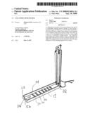
[0014]FIG. 2 is a perspective view of the collapsible book holder of FIG. 1, illustrating the generally rectangular base having a recessed storage area therein and the cover in the open position with a support beam and pair of arms in a collapsed condition substantially parallel to and pivotably attached to the cover and a clamp assembly on an edge of the cover;
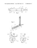
[0015]FIG. 3 is an enlarged elevational view of the clamp assembly and support beam pivot point, illustrating a substantially U-shaped clamp having a bore therethrough (shown in dotted lines) for passage of the strap and a thumbscrew for tightening thereof in the substantially U-shaped clamp;
[0016]FIG. 4 is an enlarged elevational view similar to FIG. 3, illustrating a portion of the strap tightened by the thumb screw in the clamp;
[0017]FIG. 5 is a perspective view of the collapsible book holder of FIG. 2, illustrating the support beam and the pair of arms in deployed condition and a pair of substantially U-shaped clips, one in deployed condition and one in collapsed condition; and
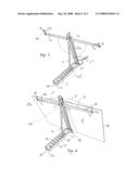
[0018]FIG. 6 is a perspective environmental view of the collapsible book holder removably mounted onto a book, illustrating the cover mounted along the spine of a book with the support beam bracing the cover, the pair of arms extending laterally behind the front and back covers of the book, and the substantially U-shaped clips holding the pages open and to the back to the front and back covers of the book.
DETAILED DESCRIPTION OF THE PREFERRED EMBODIMENTS
[0019]As shown in the drawings for purposes of illustration, the present invention is concerned with a collapsible book holder, generally designated in the accompanying drawings by the reference number 10. The collapsible book holder 10 comprises, generally, a generally rectangular base 12 with a recessed storage area 14 therein adapted to receive a support beam 16 and pair of arms 18 in collapsed condition, a generally rectangular cover 20 attached to a proximal end 22 of the generally rectangular base 12 that pivots between a closed position over the recessed storage area and an open position for deploying the support beam 16 and the pair of arms 18, and a fastening assembly 23 for removably mounting the collapsible book holder onto a book "B". The collapsible book holder may further comprise a pair of substantially U-shaped clips 28 for holding the book open.
[0020]In accordance with the present invention, and as illustrated with respect to a preferred embodiment in FIGS. 1 through 6, the collapsible book holder 10 is configured for removable mounting onto the book "B" to securely position the book in a comfortable, hands-free reading position and which may be transported on or off the book. The collapsible book holder is substantially lightweight and compact making it easier to pack, carry and store. The collapsible book holder may be molded or otherwise formed from a lightweight substantially rigid plastic for cost, convenience, strength and durability. For example, the collapsible book holder may be molded from 35% glass filled 6/6 Nylon or the like. Other materials including other suitable plastics may be used. The collapsible book holder has a preferred weight of less than eight ounces. Substantial benefit may be achieved, however, with collapsible book holders that are heavier, for example, to be used with oversized books or the like.
[0021]The generally rectangular base 12 has a bottom wall 12a, a distal endwall 12b and a pair of longitudinal sidewalls 12c defining the recessed storage area 14. The recessed storage area 14 may be upwardly open. The generally rectangular base 12 may be elongated depending on the size of the book. The generally rectangular base may be substantially rigid to withstand the weight without significant flexing and increase its durability. As shown in FIG. 2, a plurality of spaced-apart transverse ridges 30 along the bottom wall 12a and inside the recessed storage area between the longitudinal sidewalls 12c is provided for purposes as hereinafter described. The generally rectangular base 12 has a distal end 32 and the proximal end 22 to which the cover is pivotably attached. A notch 34 may be defined in the edge of the distal endwall 12b in substantially the center thereof to seat a portion of a support beam pivot assembly 36 when the book holder is in a closed, idle condition (FIG. 1) to permit the cover to snap onto the base. The base may further define a substantially cylindrical sleeve 38 outboard of the cover pivot point for purposes as hereinafter described.
[0022]The cover 20 has a top surface 20a, a bottom surface 20b, and first and second ends 20c and 20d. The cover first end 20c is pivotably connected between the longitudinal sidewalls 12c at the proximal end 22 of the base by a pair of pivot pins 40 through openings (not shown) in the proximal end of the sidewalls 12c. The cover 20 pivots along a vertical axis in a single plane. The bottom surface faces the recessed storage area of the generally rectangular base 12. The bottom surface 20b has a longitudinal channel 42 in substantially the center thereof adapted to receive the collapsed support beam 16.
[0023]The support beam 16 has a support beam first end 46 and a support beam second end 48. As shown in FIGS. 3 and 4, the support beam first end 46 may be enlarged and pivotally connected by the support beam pivot assembly 36 to the second end 20d of the cover. The support beam pivot assembly 36 comprises a pair of flanges 50 with an opening therein (not shown). The flanges 50 may be positioned within the walls of the channel 42. The flanges may be molded with the cover. A support beam pivot pin 52 may be inserted through the opening (not shown) in one of the flanges 50, through an opening (not shown) in the enlarged support beam first end 46 and through the opening (not shown) in the opposing flange to allow the support beam 16 to pivot. The support beam second end 48 is a free end. The collapsed support beam may be substantially parallel to the cover 20 and positioned in the longitudinal channel 42. The deployed support beam may be angled rearwardly from the second end 20d of the cover at varying angles, the angle adjusted by positioning the support beam second end 48 next to a selected one of the plurality of spaced-apart transverse ridges 30 in the base. This permits the angle of repose of a book "B" leaning against the book holder 10 to be varied for a comfortable reading position.
[0024]The pair of arms 18 has fixed ends and opposing free ends 54 and 56. The fixed ends 54 are pivotally attached by a pair of pivot pins 58 to the bottom surface 20a of the cover at the second end 20d thereof on each side of the support beam. The collapsed arms may be substantially parallel to the cover and positioned substantially against the bottom surface thereof with one arm on each side of the collapsed support beam as shown in FIG. 2. The deployed arms may be pivoted to a position perpendicular to the cover with one of the arms extended laterally to one side of the cover and the other arm extending laterally to the opposing side. The arms provide lateral support. The free ends 56 may include a tapered portion 60. The tapered portions 60 of the free ends may each include a first opening (not shown) for a pivot pin 60 for purposes as hereinafter described.
[0025]The substantially U-shaped clips 28 may be pivotably attached to each of the free ends 56 of the arms 18. The substantially U-shaped clips include a first wall 28a and a second wall 28b extending from opposite sides of the at least one U-shaped section. The substantially U-shaped clips include at least one aperture (not shown) in the first wall 28a for receiving the pivot pin 60. The substantially U-shaped clips 28 are pivotable between a collapsed substantially parallel position to the arms (See FIG. 5) and a deployed upward perpendicular position to the arms (See FIG. 6) for purposes as hereinafter described. The distance between the first and second walls 28a and 28b of each of the substantially U-shaped clips must be sufficiently smaller than the height of the base sidewalls 12c to enable the collapsed substantially U-shaped clips and arms to which they are connected to fit within the recessed storage area of the base and the cover to be snap closed.
[0026]The fastening assembly 23 comprises at least one strap 24 and a cooperating clamp assembly 26. The at least one strap may be leather or the like for increased durability. As shown in FIG. 1, the at least one strap may be threaded through the cylindrical sleeve 38 to provide strap portions of substantially equal length. The strap portions may be crimped together to provide a first crimped portion 62 near the cylindrical sleeve to substantially prevent the at least one strap from backing out or forwarding out of the cylindrical sleeve and to form a single strap for fastening thereafter. The opposing end of the at least one strap may be fastened into the clamp assembly 26 as hereinafter described. The at least one strap may be crimped at a second crimped portion 63 before entering the clamp assembly as shown in FIG. 3.
[0027]The clamp assembly may extend from an outer edge 66 of the second end 20d of the cover as shown in FIGS. 3 and 4. The clamp assembly 26 comprises a substantially U-shaped clamp 26a having a bore 26b therethrough and a thumbscrew 26c. The free end of the at least one strap may be threaded through the bore 26b with the thumbscrew 26c tightening the at least one strap therein (See FIGS. 3 and 4). When the collapsible book holder is in its closed, idle condition, the clamp assembly extends outboard of the cover and base. This enables the collapsible book holder to be still mounted on the book even while the collapsible book holder is in its closed, idle condition.
[0028]While the strap is shown as threaded through the cylindrical sleeve of the base, it is to be appreciated that substantial benefit may be derived from attaching the at least one strap in a different location and in some other manner. For one example only, the at least one strap may be attached to the base or the cover near the cover pivot point through eyelets, hooks or the like. While the clamp assembly is shown as the preferred fastener for the at least one strap, substantial benefit may be derived from other known fasteners and fastening arrangements. It is to be appreciated that the at least one strap may even be self-fastened without a separate fastener. It is also to be appreciated that while the at least one strap is shown as originating from near the cover pivot point, it is to be appreciated that the at least one strap may originate from the opposing end of the cover. Other known fastening assemblies may be used within the confines of the invention.
[0029]In utilizing the collapsible book holder, the base may be positioned on a surface (not shown) such as a desk, table or the like. The cover may be pivoted open (FIG. 2) and the support beam deployed from the recessed storage area in the base. The top surface of the cover may be positioned along the spine of the book (the back of the book) and removably mounted thereto with the at least one strap. The at least one strap may be pulled from the back and under the book to the front of the book and extended vertically up through the open front pages and removably fastened into the clamp assembly. The pair of arms may be deployed behind the front and back covers of the book. The adjustable support beam may be deployed with the free end thereof positioned next to a selected ridge in the base to provide the desired angle adjustment. The pair of clips may be deployed to maintain the book open. It is to be appreciated that the support beam and pair of arms may be positioned prior to or after mounting the cover to the spine of the book. It is also to be appreciated that the pair of arms may be deployed before the support beam or vice versa.
[0030]To return the collapsible book holder into its closed, idle condition (FIG. 1) for convenient transport, the clips, support beam and pair of arms may be pivoted to a collapsed position for fitting into the recessed storage area in the base before pivoting and snapping the cover closed. It is to be appreciated that the support beam may be collapsed prior to or after collapsing the pair of arms. The collapsible book holder may be collapsed into its closed, idle condition and transported while still mounted on the spine of the book. The collapsible book holder may also be removed from the book by loosening or removing the at least one strap from the clamp assembly.
[0031]From the foregoing, it is to be appreciated that the collapsible book holder 10 of the present invention provides maximum stabilization for the book, while minimizing stress and tension on the reader. The collapsible book holder holds the book at a height that does not require the reader to bend his or her neck as he or she reads and allows the angle of repose of a book leaning against it to be varied. The collapsible book holder may be easily and quickly adjusted to work with books of virtually any size and weight. The book holder is substantially lightweight enabling convenient carrying of either the book holder alone or on a book, yet durable and strong enough to support the weight of the book and stabilize its position.
[0032]Although a particular embodiment of the invention has been described in detail for purposes of illustration, various modifications may be made without departing from the spirit and scope of the invention. Accordingly, the invention is not to be limited, except as by the appended claims.
User Contributions:
comments("1"); ?> comment_form("1"); ?>Inventors list |
Agents list |
Assignees list |
List by place |
Classification tree browser |
Top 100 Inventors |
Top 100 Agents |
Top 100 Assignees |
Usenet FAQ Index |
Documents |
Other FAQs |
User Contributions:
Comment about this patent or add new information about this topic:
Images included with this patent application:
 |  |
 |
| Similar patent applications: | |
| Date | Title |
|---|---|
| 2012-12-06 | Collapsible book holder |
| 2009-02-26 | Collapsible bathroom caddy |
| 2010-03-04 | Collapsible top hanger easel |
| 2013-01-31 | Collapsible stand for supporting a portable electronic device |
| 2009-07-09 | Removable console cupholder adaptor |
| New patent applications in this class: | |
| Date | Title |
|---|---|
| 2016-05-12 | Folding travel support system for a device |
| 2014-07-24 | Configurable coaster for holding a mobile device |
| 2012-12-20 | Portable stand for an information display article |
| 2012-12-13 | Mobile computing device stand |
| Top Inventors for class "Supports" | |
| Rank | Inventor's name |
|---|---|
| 1 | Jeffrey D. Carnevali |
| 2 | Yun-Lung Chen |
| 3 | Wen-Tang Peng |
| 4 | Zheng-Heng Sun |
| 5 | Zhan-Yang Li |