Patent application title: GOLF BALL MARKER HOLDER
Inventors:
Sakae Yamashita (Hyogo, JP)
Assignees:
SAKAE SPORTS SANGYO KABUSHIKI KAISHA
IPC8 Class: AA63B5700FI
USPC Class:
473406
Class name: Games using tangible projectile golf ball position marker
Publication date: 2008-09-11
Patent application number: 20080220909
Inventors list |
Agents list |
Assignees list |
List by place |
Classification tree browser |
Top 100 Inventors |
Top 100 Agents |
Top 100 Assignees |
Usenet FAQ Index |
Documents |
Other FAQs |
Patent application title: GOLF BALL MARKER HOLDER
Inventors:
Sakae YAMASHITA
Agents:
HAHN & VOIGHT PLLC
Assignees:
SAKAE SPORTS SANGYO KABUSHIKI KAISHA
Origin: WASHINGTON, DC US
IPC8 Class: AA63B5700FI
USPC Class:
473406
Abstract:
A golf ball marker holder for holding at least one golf ball marker with
pin and one coin-shaped golf ball marker includes a body with an opening
where the markers are inserted through, wherein the body is provided with
a pin passing part on a front so that the golf ball marker with pin is
held with the pin projecting forward from the pin passing part, and the
coin-shaped golf ball marker is held at the rear of the golf ball marker
with pin. The golf ball marker holder holds two kinds of golf ball
markers of a golf ball marker with pin and a coin-shaped golf ball marker
so that a user can easily select and use a suitable marker depending on
the situation.Claims:
1. A golf ball marker holder for holding at least one golf ball marker
with pin and one coin-shaped golf ball marker comprising a body with an
opening where the markers are inserted through, wherein the body is
provided with a pin passing part on a front so that the golf ball marker
with pin is held with the pin projecting forward from the pin passing
part, and the coin-shaped golf ball marker is held at the rear of the
golf ball marker with pin.
2. The golf ball marker holder according to claim 1, wherein the body is provided with a level difference between a front side and a rear side at the bottom, so that the coin-shaped golf ball marker is partially exposed from the opening.
3. The golf ball marker holder according to claim 1, further comprising a pressing member in the body so that the golf ball marker with pin and the coin-shaped golf ball marker are respectively arranged at a front side and a rear side of the pressing member, and the golf ball marker with pin is held between the pressing member and a front wall and the coin-shaped golf ball marker is held between the pressing member and a rear wall.
4. The golf ball marker holder according to claim 2, further comprising a pressing member in the body so that the golf ball marker with pin and the coin-shaped golf ball marker are respectively arranged at a front side and a rear side of the pressing member, and the golf ball marker with pin is held between the pressing member and a front wall and the coin-shaped golf ball marker is held between the pressing member and a rear wall.
5. The golf ball marker holder according to claim 1, further comprising an attraction element on a rear side of the body for adhering the body to an appropriate object by means of a magnetic force.
6. The golf ball marker holder according to claim 2, further comprising an attraction element on a rear side of the body for adhering the body to an appropriate object by means of a magnetic force.
7. The golf ball marker holder according to claim 3, further comprising an attraction element on a rear side of the body for adhering the body to an appropriate object by means of a magnetic force.
8. The golf ball marker holder according to claim 4, further comprising an attraction element on a rear side of the body for adhering the body to an appropriate object by means of a magnetic force.
9. A base plate configured so as to be attracted to the attraction element of the golf ball marker holder according to claim 5.
10. A base plate configured so as to be attracted to the attraction element of the golf ball marker holder according to claim 6.
11. A base plate configured so as to be attracted to the attraction element of the golf ball marker holder according to claim 7.
12. A base plate configured so as to be attracted to the attraction element of the golf ball marker holder according to claim 8.
13. The golf ball marker holder according to claim 1, further comprising, on the body, a tee holding part having a cylindrical body into which a tee is inserted.
14. The golf ball marker holder according to claim 2, further comprising, on the body, a tee holding part having a cylindrical body into which a tee is inserted.
15. The golf ball marker holder according to claim 3, further comprising, on the body, a tee holding part having a cylindrical body into which a tee is inserted.
16. The golf ball marker holder according to claim 4, further comprising, on the body, a tee holding part having a cylindrical body into which a tee is inserted.
17. The golf ball marker holder according to claim 5, further comprising, on the body, a tee holding part having a cylindrical body into which a tee is inserted.
18. The golf ball marker holder according to claim 6, further comprising, on the body, a tee holding part having a cylindrical body into which a tee is inserted.
19. The golf ball marker holder according to claim 7, further comprising, on the body, a tee holding part having a cylindrical body into which a tee is inserted.
20. The golf ball marker holder according to claim 8, further comprising, on the body, a tee holding part having a cylindrical body into which a tee is inserted.
Description:
BACKGROUND OF THE INVENTION
[0001]1. Field of the Invention The present invention relates to a holder for a golf ball marker, which is used to indicate the position of a golf ball.
[0002]2. Description of the Related Art
[0003]During playing golf, when a golf ball lands on the green, a golf ball marker is placed at the landing position and the golf ball is picked up, and when the player's turn comes around again, the golf ball is replaced at the position of the golf ball marker.
[0004]Generally, as the golf ball marker, a plate-shaped plastic marker with pin, which consists of a disk-shaped part and a pin extending perpendicularly from the center of the back surface thereof, has often been used. The golf ball marker of this type has the advantage that it scarcely constitutes an obstacle to the ball lines of other players, however has drawbacks in that it is hard to find due to the undulation of the putting green because of its small and thin shape. Also, since it is difficult to give an elaborate design to this golf ball marker, a coin-shaped golf ball marker without pin, which is made of iron, brass, or the like material, has also been used recently.
[0005]At a place at a short distance from the cup, the golf ball marker tends to be located close to the golf ball markers of other players and thus plural golf ball markers are placed in small area. Therefore a relatively small and thin golf ball marker with pin is suitable for the place near the cup. On the other hand, a quite conspicuous, relatively large and thick coin-shaped golf ball marker, which is helpful for guessing the line, is suitable at a place at a long distance from the cup.
[0006]Since the player cannot swing a club with the golf ball marker in his/her hand, the golf ball marker is usually put in a pocket etc. of the slacks that the user is wearing. However, since a golf ball, tees or the like are also put in the pocket etc. together with the golf ball marker, it is time consuming to take out only the golf ball marker when necessary, and this often causes a slow play.
[0007]Thereupon, for example, a golf ball marker clip as described in Japanese Utility Model Laid-Open No. 3101456 has been invented. This golf ball marker clip is mounted on the clothes such as a hat or cap or trousers and detachably attracts a disk-shaped golf ball marker, which is made of a magnetic material, with a magnetic force. However, this golf ball marker clip can hold only the coin-shaped golf ball marker, which is made of a magnetic material, and cannot hold two kinds of golf ball markers of a golf ball marker with pin and a coin-shaped golf ball marker. Therefore, this golf ball marker clip is inconvenient for the player to use both of the two kinds of golf ball markers depending on the distance from the cup.
SUMMARY OF THE INVENTION
[0008]Accordingly, an object of the present invention is to provide a golf ball marker holder that holds two kinds of golf ball markers of a golf ball marker with pin and a coin-shaped golf ball marker so that the player can easily select and use a suitable golf ball marker of the two kinds of golf ball markers depending on the situation.
[0009]To achieve the above object, the present invention provides a golf ball marker holder for holding at least one golf ball marker with pin and one coin-shaped golf ball marker comprising a body with an opening where the markers are inserted through, wherein the body is provided with a pin passing part on the front so that the golf ball marker with pin is held with the pin projecting forward from the pin passing part, and the coin-shaped golf ball marker is held at the rear of the golf ball marker with pin. The golf ball marker with pin has the pin extending perpendicularly from a plate-shaped part to be inserted into a lawn and fix the marker itself so as to prevent the marker from swelling out, whereas the coin-shaped golf ball marker has no pin.
[0010]Preferably, the body is provided with a level difference between the front side and the rear side at the bottom, so that the coin-shaped golf ball marker is partially exposed from the opening.
[0011]Further preferably, a pressing member is provided in the body so that the golf ball marker with pin and the coin-shaped golf ball marker are respectively arranged at a front side and a rear side of the pressing member, and the golf ball marker with pin is held between the pressing member and a front wall and the coin-shaped golf ball marker is held between the pressing member and a rear wall.
[0012]Still further preferably, an attraction element for adhering the body to an appropriate object by means of a magnetic force is provided on the rear surface side of the body so that the golf ball maker holder may be adhered to the appropriate object by means of a magnetic force.
[0013]Also, the golf ball marker holder can be used together with a base plate that is configured so as to be attracted to the attraction element.
[0014]The golf ball marker holder in accordance with the present invention, which has the above-described configuration, holds two kinds of golf ball markers of the golf ball marker with pin and the coin-shaped golf ball marker. Therefore, the player can easily select and use a suitable golf ball marker of the two kinds of golf ball markers depending on the situation.
[0015]If the level difference is provided between the front side and the rear side at the bottom in the body, so that the coin-shaped golf ball marker is partially exposed from the opening, it becomes easier to pick up and take out the coin-shaped golf ball marker.
[0016]If the pressing member is provided in the body so that the golf ball markers are respectively arranged at the front side and the rear side of the pressing member, and the golf ball marker with pin is held between the pressing member and a front wall and the coin-shaped golf ball marker is held between the pressing member and a rear wall, even when, for example, the user bends down, the golf ball markers can be prevented from coming off the holder unexpectedly, and can be kept in a stably held state.
[0017]Also, if the attraction element for adhering the body to an appropriate object by means of a magnetic force is provided on the rear side of the body, and the base plate configured to be attracted to an attraction element is used, the golf ball marker holder can be attached to anywhere appropriate of various kinds of clothes and thereby becomes convenient.
BRIEF DESCRIPTION OF THE DRAWINGS
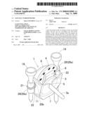
[0018]FIG. 1 is a perspective view of a golf ball marker holder in accordance with an embodiment of the present invention and two kinds of golf ball markers;
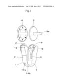
[0019]FIG. 2 is an explanatory view showing a configuration of the interior of a golf ball marker holder in accordance with an embodiment of the present invention and an attraction element;
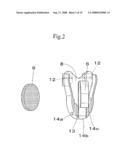
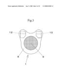
[0020]FIG. 3 is a back view of a golf ball marker holder in accordance with an embodiment of the present invention;
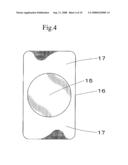
[0021]FIG. 4 is an explanatory view of a base plate configured so as to be attracted to an attraction element of a golf ball marker holder in accordance with an embodiment of the present invention;
[0022]FIG. 5 is a perspective view showing a state in which a golf ball marker holder in accordance with an embodiment of the present invention is attached;
[0023]FIG. 6 is a sectional view showing a state in which a golf ball marker holder in accordance with an embodiment of the present invention is attached;
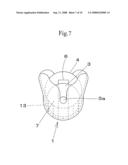
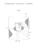
[0024]FIG. 7 is an explanatory view showing a state in which golf ball markers are accommodated in a golf ball marker holder in accordance with an embodiment of the present invention;
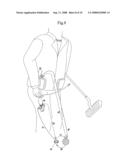
[0025]FIG. 8 is an explanatory view showing a state in which a golf ball marker holder in accordance with an embodiment of the present invention is used;
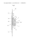
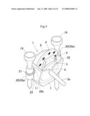
[0026]FIG. 9 is a perspective view of a golf ball marker holder with tee holding part in accordance with an embodiment of the present invention; and
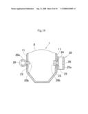
[0027]FIG. 10 is a sectional view of the body and the tee holding parts of a golf ball marker holder.
DETAILED DESCRIPTION OF THE PREFERRED EMBODIMENTS
[0028]A preferred embodiment of the present invention will now be described with reference to the accompanying drawings.
[0029]FIG. 1 is a perspective view of a golf ball marker holder in accordance with the embodiment of the present invention and two kinds of golf ball markers, FIG. 2 is an explanatory view showing a configuration of the interior of the golf ball marker holder shown in FIG. 1 and an attraction element 9; and FIG. 3 is a back view of the golf ball marker holder.
[0030]This golf ball marker holder can hold at least one golf ball marker 3 with pin and one coin-shaped golf ball marker 4 by inserting them through an opening 2 in a body 1. The golf ball marker holder is provided with a pin passing part 5 on the front side of the body 1, and is configured so as to hold the golf ball marker 3 with pin in the state in which a pin 3a projects towards the front through the pin passing part 5 and hold the coin-shaped golf ball marker 4 at the rear of the golf ball marker 3 with pin.
[0031]The golf ball marker 3 with pin consists of a plastic-made disk-shaped part and the pin 3a extending perpendicularly from the center of the back surface thereof.
[0032]The coin-shaped golf ball marker 4 is a coin-shaped or medal-shaped marker with decoration on the surface as necessary, which is made of iron, brass, or the like material, and which has no pin. Commonly used golf ball markers can be used as the golf ball marker 3 with pin and the coin-shaped golf ball marker 4, and the shape and material thereof are not limited to the above-described ones.
[0033]The body 1 of the golf ball marker is of a small container shape with the opening 2 at the upper part including a wall 7 on the front side, a wall 8 on the rear side and a wall 11 formed therebetween. In the body 1, a space capable of accommodating at least two golf ball markers is provided between the wall 7 on the front side and the wall 8 on the rear side. The wall 7 on the front side and the wall 8 on the rear side each have a substantially semicircular part with a radius slightly larger than the radius of the golf ball marker, and the upper parts of the walls can be formed to have a shape spreading like a funnel so as to make it easy to put in and take out the golf ball marker.
[0034]The body 1 can be manufactured of an appropriate material such as plastics, metal, or leather. Although the body 1 shown in the figures is integrally molded as a whole, the body 1 can also be formed using a plurality of members by bonding or sewing.
[0035]The wall 7 on the front side is formed with a notch ranging from the center upper end to the central part, and this notch is used as the pin passing part 5. The pin passing part 5 has an inverse chevron shape spreading upward so as to be capable of guiding the pin 3a of the golf ball marker downward smoothly. Also, the golf ball marker 3 with pin accommodated in the body 1 can be taken out easily by pinching the pin 3a with the user's fingers and pulling it upward.
[0036]Onto the wall 8 on the rear side, a magnet as an attraction element 9 for adhering the body 1 to an appropriate object by means of a magnetic force is bonded to the outside surface thereof. This golf ball marker holder can be adhered to an appropriate object by means of the magnetic force of the attraction element 9 with a base plate 10, described later. Further, in protruding portions in the right and left upper parts of the wall 8 on the rear side, through holes 12 are provided, so that the golf ball marker holder can be attached to the clothes or the like by using safety pins or strings with passing through the through holes 12.
[0037]At the bottom of the body 1, a level difference is provided between the front side and the rear side. This level difference is formed by a bottom raising part 13 on the rear side as seen in FIG. 2. The bottom raising part 13 can have an arbitrary shape as long as it can support the lower end edge of the coin-shaped golf ball marker 4. Because of this level difference, the coin-shaped golf ball marker 4 can be held in a state of being partially exposed from the opening 2.
[0038]In the center and at the right and left of the body 1, there are formed three longitudinal holes 14a, 14b and 14c that penetrate the bottom raising part 13 and are open to the bottom. By these longitudinal holes 14a, 14b and 14c, water intruding into the body 1 can be drained, or the distortion of the body 1 can be absorbed.
[0039]In the body 1, a pressing member 6 is provided. The pressing member 6 is formed by a plate spring having an appropriate size, which is bent into a hairpin shape to the front, and is fixed by being inserted into the central longitudinal hole 14b. The pressing member 6 can also be formed of a flexible and elastic material such as urethane.
[0040]In the body 1, the golf ball markers 3 and 4 are respectively disposed at the front side and the rear side of the pressing member 6. Also, the golf ball markers 3 and 4 are held under pressure between the pressing member 6 and the walls 7 and 8 on the front side and the rear side. Thereby, for example, even when the user bends down, the golf ball markers 3 and 4 do not come off the body 1 unexpectedly, and can be kept in a stably held state.
[0041]FIG. 4 is an explanatory view of a base plate 10 configured so as to be attracted to the attraction element 9 of the golf ball marker holder. The base plate 10 is formed by bonding an iron sheet 15 to an appropriate base material 16 such as a cloth. The iron sheet 15 is preferably plated for rustproofing. The member constituting the base plate 10 is not limited to the above-described member, and any member that is configured so that the base plate 10 is attracted to the attraction element 9 may be used. The iron sheet 15 can be replaced with a magnet. In this case, an iron sheet is used as the attraction element 9 of the body 1.
[0042]The base material 16 is provided with a sticking part 17 to which a pressure-sensitive adhesive is applied in the upper and lower parts of the iron sheet 15. The sticking part 17 is covered by a release paper, and at the time of use, by peeling off the release paper, the base plate 10 can be stuck and fixed to an appropriate location of the clothes such as slacks, a jacket, or rainwear.
[0043]The attachment of the golf ball marker holder to the clothes does not rely on only the pressure-sensitive adhesive of the sticking part 17. The pressure-sensitive adhesive is merely an auxiliary means. Once the golf ball marker holder is mounted, the base plate 10 and the golf ball marker holder should keep a state of stably being attracted to each other by means of the attraction of the attraction element 9 so that the golf ball marker holder does not drop easily. When the adhesive power of the sticking part 17 weakens, a double faced adhesive tape may be used as a substitute for the pressure-sensitive adhesive.
[0044]FIG. 5 is a perspective view showing a state in which the golf ball marker holder is attached to the outside of a cloth 18 of the clothes by affixing the base plate 10 (not shown) to the backside of the cloth 18, FIG. 6 is a sectional view showing the above-described state, and FIG. 7 is an explanatory view showing a state in which the golf ball markers 3 and 4 are accommodated in the golf ball marker holder. One golf marker 3 with pin and one coin-shaped golf ball marker 4 are inserted and held in the body 1 of the golf ball marker holder.
[0045]The golf ball markers 3 and 4 are arranged in the body 1 in a state in which the respective disk-shaped part thereof is erected in parallel with the front and rear surfaces of the body 1. That is to say, the golf marker 3 with pin is arranged so that the pin 3a thereof projects through the pin passing part 5, and the coin-shaped golf ball marker 4 is arranged at the rear of the disk-shaped part of the golf ball marker 3 with pin so as to be in parallel with the disk-shaped part of the golf ball marker 3 with pin.
[0046]Since this golf ball marker holder can hold two kinds of golf ball markers 3 and 4, the holder is very convenient to use. That is to say, since the golf ball marker holder can be attached to the outside of the clothes as described above, the golf ball markers 3 and 4 can be taken out more quickly as compared with the case where the golf ball markers 3 and 4 are put in a pocket of the slacks that the user is wearing, so that the progress of play can be facilitated.
[0047]Moreover, a suitable golf ball marker of the two kinds of golf ball markers 3 and 4 can easily be selected and used depending on the situation. For example, at a place at a short distance from the cup, where the golf ball marker tends to be located close to the golf ball markers of other players and thus plural golf ball markers are placed in small area, the relatively small and thin golf ball marker 3 with pin is used. On the other hand, at a place at a long distance from the cup, the relatively large and thick coin-shaped golf ball marker 4 is used.
[0048]Also, the user can appropriately choose where to attach the golf ball marker holder on the clothes, at which the play is not affected. In particular, if the golf ball marker holder is attached to around the knee on the slacks, as shown in FIG. 8, a series of motions for setting of the golf ball marker and picking up of the ball (sequence of a, b, c and d in FIG. 8) and a series of motions for resetting of the golf ball marker and the ball and transferring to putting (sequence of e, f, g, h and i in FIG. 8) can be performed quickly without wasteful motion, so that a problem of slow play can be solved effectively.
[0049]Further, the material for the coin-shaped golf ball marker 4 is not limited to a material that is attracted by a magnet. The coin-shaped golf ball marker 4 can be manufactured of any of various types of metals etc. The marker 4 having an appropriate thickness and weight according to the user's taste can be used.
[0050]Also, since the base plate 10 can be hidden on the inside invisible from the outside of the clothes, the appearance of the golf ball marker holder becomes neat. It is also possible to attach the golf ball marker holder to the metal part of a bag or a cart without using the base plate 10.
[0051]Further, for this golf ball marker holder, as shown in FIG. 9 (perspective view), the body 1 can be provided with tee holding parts 20 for insertingly holding tees 19. Thereby, the golf ball marker holder becomes more convenient to use because a user can select not only the golf ball marker but also the tee.
[0052]FIG. 10 is a sectional view of the body 1 and the tee holding parts 20 of the golf ball marker holder. For ease of understanding of the construction, FIG. 10 shows the right and left tee holding parts 20 in which an elastic member 21, described later, is removed. Also, FIG. 10 shows the left-hand side tee holding part 20 which is in the middle of being fixed to the body 1 and the right-hand side tee holding part 20 which has been fixed to the body 1.
[0053]The tee holding part 20 is made of a synthetic resin, and has a cylindrical body 20a shorter than the length of a general tee. The inside diameter of the upper end of the cylindrical body 20a is slightly smaller than the diameter near the upper end part of the tee 19 so that the tee 19 is held in a state in which a portion near the upper end part of the tee 19 inserted as shown in FIG. 9 projects upward from the tee holding part 20. It is preferable that the cylindrical body 20a be configured so that the inside diameter at the upper end thereof is larger than the inside diameter at the lower end thereof for easy insertion and removal of the tee 19.
[0054]The tee holding part 20 has an attaching/detaching part 20b projecting from the outer peripheral surface of the cylindrical body 20a of the tee holding part 20. The attaching/detaching part 20b extends substantially at right angles to the outer peripheral surface of the cylindrical body 20a, and has a rod-shaped part, which extends in parallel with the cylindrical body 20a, at the tip end.
[0055]At positions close to the rear surface on the right and left walls 11 of the body 1 of the golf ball marker holder, holes 22 for inserting the attaching/detaching parts 20b are formed. The hole 22 has a transversely long rectangular shape so that when the tee holding part 20 is turned into a transversely directed state like the tee holding part 20 shown on the left-hand side of FIG. 10, the attaching/detaching part 20b can be attached or detached, and when the tee holding part 20 is turned into a longitudinally directed state like the tee holding part 20 shown on the right-hand side of FIG. 10, the attaching/detaching part 20b cannot be attached or detached. Either end parts of the attaching/detaching part 20b can be directed upward to attach or detach the tee holding part 20. Therefore, if the cylindrical body 20a is made to have different sized inside diameters at one end and the other, the user can appropriately choose which end is turned up according to the thickness or shape of the tee being used and thus this improves the convenience.
[0056]Also, in the inner surface of the wall 11, there is formed a concavity 23 that intersects the hole 22 in a cross shape, so that the rod-shaped part of the attaching/detaching part 20b in the state in which the tee holding part 20 is directed in the longitudinal direction engages with the concavity 23.
[0057]Onto the outer peripheral surface of the cylindrical body 20a of the tee holding part 20, the ring-shaped elastic member 21 is attached. In the outer peripheral surface of the cylindrical body 20a, grooves 24, 25 and 26 each having an appropriate length for receiving the elastic member 21, are formed near the upper and lower part of the root of the attaching/detaching part 20b and on the opposite side to the attaching/detaching part 20b.
[0058]FIG. 9 shows a state in which the elastic member 21 is attached to the cylindrical body 20a with being received in the groove 24 near the upper part of the root of the attaching/detaching part 20b. However, it is also possible to attach the elastic member 21 to the cylindrical body 20a with being received in the groove 25 near the lower part of the root of the attaching/detaching part 20b.
[0059]The groove 26 on the opposite side to the attaching/detaching part 20b reaches a depth penetrating the peripheral wall of the cylindrical body 20a, so that the elastic member 21 projects to the inside and comes into contact with the tee 19.
[0060]The elastic member 21 is formed of a material having elasticity and flexibility such as rubber. Since the elastic member 21 comes into contact with the tee 19 at the place where the groove 26 penetrates, even if the user moves his/her body during the play, the tee 19 is prevented from being undesirably come off. Even if the thickness of the tee 19 is slightly smaller than the inside diameter of the tee holding part 20, the tee 19 is held stably by the contact of the elastic member 21 with the tee 19, so that many different sized tees can be held.
[0061]Also, the elastic member 21 is held between the portion near the root of the attaching/detaching part 20b and the body 1 of the golf ball marker holder, and acts the cylindrical body 20a to push outwardly. Therefore, the engagement state between the concavity 23 and the rod-shaped part of the attaching/detaching part 20b is kept firmly.
[0062]The tee holding part 20 need not be provided on both right and left sides of the body 1 as shown in the figures. The tee holding part 20 may be provided on one side only. Also, the size and shape of the tee holding part 20 can be modified as necessary according to the tee used. Further, the inner surface (the surface with which the coin-shaped golf ball marker 4 comes into contact) of the wall 8 on the rear side of the body 1 may be tilted so that the coin-shaped golf ball marker 4 leans against the inner surface. Further, the inner surfaces of the wall 7 on the front side and the wall 8 on the rear side of the body 1 may be tilted so that the golf ball markers 3 and 4 are held in a state of leaning forward, and the opening 2 may be formed to have a wide opening, so that the golf ball markers 3 and 4 can be put in and taken out easily. If the inner surface of the wall 8 is tilted forward, the distance between the upper part of the coin-shaped golf ball marker 4 and the clothes is increased and therefore it becomes easy to pick up the coin-shaped golf ball marker 4.
User Contributions:
comments("1"); ?> comment_form("1"); ?>Inventors list |
Agents list |
Assignees list |
List by place |
Classification tree browser |
Top 100 Inventors |
Top 100 Agents |
Top 100 Assignees |
Usenet FAQ Index |
Documents |
Other FAQs |
User Contributions:
Comment about this patent or add new information about this topic:
Images included with this patent application:
 |  |
 |  |
 |  |
 |  |
 |  |
 |
| Similar patent applications: | |
| Date | Title |
|---|---|
| 2010-02-25 | Golf ball marker and holder |
| 2012-05-31 | Green repair tool, golf accessory, and combination golf ball marker retention and green repair tool device |
| 2008-09-18 | Golf balls having a low modulus hnp layer and a high modulus hnp layer |
| 2008-10-02 | Golf balls having a low modulus hnp layer and a high modulus hnp layer |
| 2008-10-02 | Golf balls having a low modulus hnp layer and a high modulus hnp layer |
| New patent applications in this class: | |
| Date | Title |
|---|---|
| 2016-05-26 | Systems and methods for determining optimum putting speed and angle |
| 2016-01-28 | Marker to determine a golf ball's original position on a course |
| 2015-12-31 | Digital compass ball marker |
| 2015-03-05 | Digital compass ball marker |
| 2015-02-19 | System for indicating a position of a golf ball having fallen on a screen on a real green and a method of playing golf using the same |
| Top Inventors for class "Games using tangible projectile" | |
| Rank | Inventor's name |
|---|---|
| 1 | Michael J. Sullivan |
| 2 | Brian Comeau |
| 3 | Derek A. Ladd |
| 4 | David A. Bulpett |
| 5 | Mark L. Binette |