Patent application title: Stackable Liquid Container
Inventors:
Carl T. Eiten (Byron, IL, US)
Matthew J. Simpson (Tecumseh, MI, US)
Assignees:
Dean Intellectual Property Services II, L.P.
IPC8 Class: AB65D8562FI
USPC Class:
206504
Class name: Special receptacle or package structural features for vertical stacking, i.e., similar receptacles having specified means for lateral stacking
Publication date: 2008-09-11
Patent application number: 20080217200
Inventors list |
Agents list |
Assignees list |
List by place |
Classification tree browser |
Top 100 Inventors |
Top 100 Agents |
Top 100 Assignees |
Usenet FAQ Index |
Documents |
Other FAQs |
Patent application title: Stackable Liquid Container
Inventors:
Carl T. Eiten
Matthew J. Simpson
Agents:
BAKER BOTTS L.L.P.
Assignees:
Dean Intellectual Property Services II, L.P.
Origin: DALLAS, TX US
IPC8 Class: AB65D8562FI
USPC Class:
206504
Abstract:
In one embodiment according to the present disclosure, a liquid container
generally includes a base member, an annular sidewall member, a neck
member, a spout, and a handle. The annular sidewall member is attached to
and extends upwardly from the base member. The neck member couples the
annular sidewall member to the spout. The base member has a recessed
portion that extends upwardly into the container such that the base
member may rest upon the neck member of another container.Claims:
1. A container for liquids, comprising:a base member;an annular sidewall
member that is attached to and extends upward from the base member;a
spout for receiving an associated closure cap for removable placement on
and off of the spout;an upwardly converging neck member that couples the
annular sidewall member and the spout; anda handle that is attached to
the container proximate the neck member;wherein the base member has a
recessed portion that extends upwardly into the container such that the
base member may rest upon the neck member of another container, the
recessed portion having a lower contour that generally conforms to at
least a portion of an upper contour formed by the neck member and closure
cap when selectively disposed on the spout;wherein the neck member has a
support projection that extends upwards from the neck member, the support
projection extending over at least a radial portion of the neck member,
wherein the neck member comprises at least one rib that extends from the
spout to the annular sidewall member, the handle being radially spaced
apart on the neck member from the at least one rib; andwherein the
annular sidewall member has a sidewall protruding portion and a sidewall
indented portion, the sidewall protruding portion having an outer contour
that generally conforms to an inner contour of the sidewall indented
portion, the sidewall protruding portion and the sidewall indented
portion each extending from the base member to the neck member of the
container.
2. The container of claim 1, wherein the at least one rib is three ribs.
3. The container of claim 1, wherein the support projection is generally semi-circular in shape.
4. The container of claim 1, wherein the base member is generally square in shape.
5. The container of claim 1, wherein the spout is centrally disposed over the base member.
6. A container for liquids, comprising:a base member;an annular sidewall member that is attached to and extends upward from the base member;a spout for receiving an associated closure cap for removable placement on and off of the spout;an upwardly converging neck member that couples the annular sidewall member and the spout; anda handle that is attached to the container proximate the neck member;wherein the base member has a recessed portion that extends upwardly into the container such that the base member may rest upon the neck member of another container.
7. The container of claim 6, wherein the recessed portion has a lower contour that generally conforms to at least a portion of an upper contour formed by the neck member and closure cap when selectively disposed on the spout.
8. The container of claim 6, wherein the neck member comprises at least one rib that extends from the spout to the annular sidewall member, the handle member being radially spaced apart on the neck member from the at least one rib.
9. The container of claim 8, wherein the at least one rib is three ribs.
10. The container of claim 6, wherein the neck member has a support projection that extends upwards from the neck member, the support projection extending over at least a radial portion of the neck member.
11. The container of claim 10, wherein the support projection is generally semi-circular in shape.
12. The container of claim 6, wherein the annular sidewall member has a sidewall protruding portion and a sidewall indented portion, the sidewall protruding portion having an outer contour that generally conforms to an inner contour of the sidewall indented portion.
13. The container of claim 12, wherein the sidewall protruding portion and the sidewall indented portion each extends from the base member to the neck member.
14. The container of claim 13, wherein the sidewall protruding portion and the sidewall indented portion are generally linear in shape.
15. The container of claim 6, wherein the spout is centrally disposed over the base member.
16. The container of claim 6, wherein the base member is generally square in shape.
17. A container for liquids, comprising:a base member;an annular sidewall member that is attached to and extends upward from the base member;a spout for receiving an associated closure cap for removable placement on and off of the spout;an upwardly converging neck member that couples the annular sidewall member and the spout; anda handle that is attached to the container proximate the neck member;wherein the annular sidewall member has a sidewall protruding portion and a sidewall indented portion, the sidewall protruding portion having an outer contour that generally conforms to an inner contour of the sidewall indented portion.
18. The container of claim 17, wherein the sidewall protruding portion and the sidewall indented portion each extend from the base member to the neck member.
19. The container of claim 17, wherein the sidewall protruding portion and the sidewall indented portion are generally linear in shape.
20. The container of claim 17, wherein the base member has a recessed portion that extends upwardly into the container such that the base member may rest upon the neck member of another liquid container.
Description:
RELATED APPLICATIONS
[0001]This application claims the benefit of priority under 35 U.S.C. §119(e) of U.S. Provisional Application Ser. No. 60/893,061, filed Mar. 5, 2007, and entitled "STACKABLE LIQUID CONTAINER."
TECHNICAL FIELD OF THE DISCLOSURE
[0002]This disclosure relates in general to containers and, more particularly, to a stackable liquid container providing enhanced structural integrity.
BACKGROUND OF THE DISCLOSURE
[0003]Liquid products are typically distributed from a manufacturer to consumers in liquid containers that may be easily handled and transported by the consumer. These liquid containers are generally formed of a liquid impermeable material that may be, for example, a thermoplastic, such as polyethylene or other similar material. The capacity of these liquid containers may be several gallons or less such that handling and transport of the containers do not create an undue burden to the consumer.
[0004]Known liquid product distribution practices have utilized ancillary support structures, such as the commonly known "milk crate." The milk crate is a generally rigid structure into which a number of liquid containers may be placed and has an upper rim that provides for support of another milk crate disposed above. The milk crate enables stacking of multiple liquid containers, one upon another, by alleviating downward directed forces from the liquid containers stored inside.
SUMMARY OF THE DISCLOSURE
[0005]In one embodiment according to the present disclosure, a liquid container generally includes a base member, an annular sidewall member, a neck member, a spout, and a handle. The annular sidewall member is attached to and extends upwardly from the base member. The neck member couples the annular sidewall member to the spout. The base member has a recessed portion that extends upwardly into the container such that the base member may rest upon the neck member of another container.
[0006]In another embodiment, a liquid container generally includes a base member, an annular sidewall member, a neck member, a spout, and a handle. The annular sidewall member is attached to and extends upwardly from the base member. The neck member couples the annular sidewall member to the spout. The annular sidewall member has a sidewall protruding portion and a sidewall indented portion, the sidewall protruding portion having an outer contour that generally conforms to an inner contour of the sidewall indented portion.
[0007]Embodiments of the disclosure may provide numerous technical advantages. Some, none, or all embodiments may benefit from the below described advantages. According to one embodiment, the liquid container may have a recessed portion that projects upwardly from the base member such that the base member may rest upon the neck member of another container. This structural feature may provide distribution of weight that is applied from one liquid container disposed upon another to be distributed over a relatively larger portion of the liquid container than known liquid container designs. The enhanced structural integrity provided by the recessed portion may enable stacking multiple liquid containers, one upon another, without the use of ancillary support structures, such as milk crates.
[0008]Other technical advantages will be apparent to one of skill in the art.
BRIEF DESCRIPTION OF THE DRAWINGS
[0009]A more complete understanding of embodiments of the disclosure will be apparent from the detailed description taken in conjunction with the accompanying drawings in which:
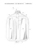
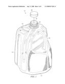
[0010]FIG. 1 is a perspective view of one embodiment of a liquid container according to the teachings of the present disclosure;
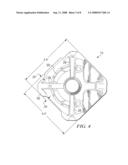
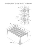
[0011]FIG. 2 is a bottom view of the embodiment of FIG. 1;
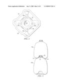
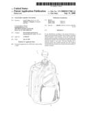
[0012]FIG. 3 is a cut-away, elevational view of two liquid containers according to the embodiment of FIG. 1 in which one liquid container is stacked on top of another;
[0013]FIG. 4 is a top view of the embodiment of FIG. 1;
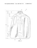
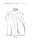
[0014]FIG. 5 is a front side elevational view of the embodiment of FIG. 1;
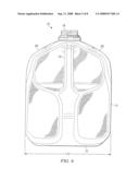
[0015]FIG. 6 is a rear side elevational view of the embodiment of FIG. 1;
[0016]FIG. 7 is a right side elevational view of the embodiment of FIG. 1;
[0017]FIG. 8 is a left side elevational view of the embodiment of FIG. 1;
[0018]FIG. 9 is a top view of two liquid containers according to the embodiment of FIG. 1 that are stacked together in a side-by-side configuration; and
[0019]FIG. 10 is a perspective view of several liquid containers of the embodiment of FIG. 1 that have been stacked together in a collapsible crate.
DETAILED DESCRIPTION OF EXAMPLE EMBODIMENTS OF THE DISCLOSURE
[0020]As described previously, known liquid containers for consumer products such as milk, may be stored in milk crates, due to their relatively delicate nature. These milk crates protect the liquid container from damage by alleviating downward directed forces from other items stored on top. This is because known liquid container designs may not be configured to support the weight of other liquid containers. Usage of these milk crates, however, is a generally inefficient practice. That is, these milk crates serve little purpose to the consumer and therefore are transported back to the manufacturer following distribution to the consumer. It would therefore, be beneficial to provide a liquid container that alleviates the costs and burden associated with shipping and storage of a plurality of liquid containers in known ancillary support structures, such as milk crates.
[0021]FIG. 1 shows one embodiment of a liquid container 10 that may provide a solution to these needs as well as other needs. Liquid container 10 has a number of features that may enable stacking of multiple containers 10, one upon another. In one embodiment, the container 10 of the present disclosure provides for the stacking of multiple containers 10 one upon another, without the need for extraneous ancillary support structures, such as known milk crate designs.
[0022]Liquid container 10 generally includes a base member 12, an annular sidewall member 14, a neck member 16, a spout 18, and a handle 24. The annular sidewall member 14 is integrally formed and extends upwardly from the base member 12. The upper end of the annular sidewall member 14 is interconnected to the spout 18 by the generally frusto-conical shaped, upwardly converging neck member 16. Together, the base member 12, annular sidewall member 14, neck member 16, and spout 18 forms a chamber for the storage and containment of a liquid therein. In a normal upright orientation, the base member 12 lies in a generally horizontal orientation such that the spout 18 exists at the apex of the liquid container 10. The spout 18 comprises a generally hollow opening for pouring liquids to and from the container 10.
[0023]The spout 18 may also have an associated closure cap 20 for removable placement over the spout 18. In the particular embodiment shown, thread-like ridges 22 may be included on the outer periphery of the spout 18 for securing the closure cap 20 to the spout 18. However, the cap 20 may comprise any type of industry standard dairy cap having screw-on, snap-on, or similar type selective attachment means. Caps of this nature may be available from Portola, located in Batavia, Ill.
[0024]FIG. 2 is a bottom view showing various features of the base member 12. Base member 12 has a recessed portion 26 and a number of slots 32. The recessed portion 26 and slots 32 project upwardly from the base member 12 for reasons to be described below. With the exception of the recessed portion 26 and slots 32, the base member 12 is generally flat in shape for relatively stable placement of the liquid container 10 on a flat surface, such as a tabletop.
[0025]FIG. 3 is a cut away, elevational view showing the arrangement of one liquid container 10a that is stacked on top of another liquid container 10b. Support for another liquid container 10a on top of liquid container 10b may be provided by recessed portion 26. The recessed portion 26 projects upwardly into the container 10, such that the base member 12 of liquid container 10a may rest upon the neck member 16 of liquid container 10b. Because the recessed portion 26 allows the base member 12 of one container 10a to rest upon the neck member 16 of another container 10b, the weight of container 10a and its liquid contents may be generally evenly distributed around the upper surface of the neck member 16 of container lob in close proximity to the annular sidewall member 14.
[0026]The spout 18 is significantly smaller in diameter than the annular sidewall member 14 such that the neck member 16 converges from the annular sidewall member 14 to the spout 18 in a generally frusto-conical shape. This upwardly converging shape however, does not easily lend itself to transferring downward directed forces caused by the weight of liquid container 10a placed directly upon the spout 18 of container 10b. The teachings of the present disclosure provide a solution to this need via a liquid container 10 having a base member 12 that is configured to rest directly upon the neck member 16 of another container lob such that downward directed forces caused by the weight of the container 10a and its contents, are efficiently transferred to the annular sidewall member 14 of the container 10b disposed underneath.
[0027]FIG. 4 shows a top view of the embodiment of FIG. 1. In one embodiment, the neck member 16 may have at least one rib 28 that extends from the spout to the annular sidewall member 14. In this particular embodiment, three ribs 28 are configured on the neck member 16. It should be appreciated however, that any quantity of ribs 28 may be utilized within the teachings of the present disclosure. The ribs 28 may provide enhanced structural rigidity by transferring localized forces incident upon the neck member onto the annular sidewall member 14. The ribs 28 may also transfer forces incident upon the spout 18 toward the annular sidewall member 14. The ribs 28 may operate in conjunction with handle 24 in order to form a relatively robust structure for distributing weight placed upon the liquid container 10 in a generally even manner. In order to evenly distribute the weight around the entire periphery of the annular sidewall member 14, the ribs 28 and handle 24 may be evenly spaced around the neck member 16 of the liquid container 10.
[0028]In another embodiment, the neck member 16 may also have a support projection 30. Support projection 30 extends upwardly from the neck member 16 and extends over at least a radial portion of the neck member 16. In one embodiment, support projection 30 is generally semi-circular in shape. Support projection 30 may provide a relatively stable support surface for the base member 12 of another liquid container 10 placed on top. In certain embodiments, support projection 30 may enhance the stability of one container 10 when placed on top of another container 10 by supporting the container 10 at the base member 12, which is generally flat in shape.
[0029]In one embodiment, the recessed portion 26 has a contour that generally conforms to the contour formed by the neck member 16, closure cap 20, ribs 28, handle 24, support projection 30, and any other structural member that extends generally upwardly from the neck member 16 or spout 18 of the liquid container 10. The ribs 28 may be configured on neck member 16 such that they at least partially fit into cavities formed by slots 32 in base member 12. When fitted into slots 32, the ribs 28 may prevent rotation of one particular liquid container 10 that is stacked upon another liquid container 10.
[0030]Reference will now be made to FIGS. 5 through 8 showing front, rear, right, and left side elevational views, respectively, of the embodiment of FIG. 1. In one embodiment, annular sidewall member 14 has a sidewall indented portion 34 and a sidewall protruding portion 36 for improved lateral support of another liquid container 10 that is stacked in a side-by-side arrangement. The sidewall protruding portion 36 extends from the base member 12 to neck member 16 and is generally convex in shape to fit at least partially inside of the sidewall indented portion 34 of another container 10. In the particular embodiment shown, the sidewall indented portion 34 and sidewall protruding portion 36 is generally linear in shape from base member 12 to neck member 16. It should be appreciated, however, that sidewall indented portion 34 and sidewall protruding portion 36 may have any shape that allows at least a portion of the sidewall protruding member 36 to rest inside at least a portion of the sidewall indented portion 34.
[0031]FIG. 9 is a top view of two liquid containers 10 that are stacked in a side-by-side configuration. As can be seen, sidewall protruding portion 36 fits at least partially into sidewall indented portion 34. Certain embodiments incorporating sidewall protruding portion 36 and sidewall indented portion 34 may provide an advantage in that lateral stability of one liquid container 10 relative to another may be enhanced when stacked in a side-by-side configuration.
[0032]Certain embodiments incorporating a sidewall indented portion 34 and a sidewall protruding portion 36 may provide an advantage in that removal of one particular liquid container 10 from a number of liquid containers 10 stacked together may be enhanced by encouraging a lifting action upwards on the liquid container 10 rather than using a lateral movement action. Advantages that may be provided by embodiments incorporating sidewall indented portion 34 and sidewall protruding portion 36 may include enhanced loading capability of the annular sidewall member 14 from downward directed forces on the neck member 16.
[0033]FIGS. 4, 6, and 8 show several dimensions of one embodiment of liquid container 10 according to the teachings of the present disclosure. The liquid container 10 as shown has a generally square-shaped base member 12 having an overall height of 9.752 inches, a width of 6.00 inches, and depth of 6.00 inches. The diagonal width of the container 10 may be 7.27 inches. For dimensioning purposes, the container 10 may have a neck split 38 and a bottom split 39. The spout 18 may be 38 millimeters in diameter and extends 0.80 inches from the neck split 38. The base of the spout 18 is 1.189 inches above a cavity formed by handle 24. The neck split 38 exists 7.184 inches from the bottom split 39. The bottom split 39 is 1.768 inches above the base member 12. The indented member 34 extends 0.28 inches into the annular sidewall member 14 and the protrusion 36 extends 0.25 inches out of the annular sidewall member 14.
[0034]The particular liquid container 10 as disclosed is configured to have a fill capacity of 128.0 fluid ounces and an overflow capacity of 128.7 fluid ounces. It will be understood however, that a container having other capacities could be constructed using the teachings of this disclosure. Moreover, containers having different sizes, configurations, and/or fill capacities other than 128.0 fluid ounces may have dimensions other than those previously described.
[0035]The container 10 may be particularly suited for transport and distribution of various types of liquid products from a manufacturer to consumers. The type of liquid products may include consumable foodstuffs such as juice, water, milk, and the like, or other types of liquids such as chemical formulations for home, automotive, commercial, or industrial use. The liquid container 10 may be constructed of a high density polyethylene (HDPE) plastic material, which is generally "food safe", for storage of human consumable liquids. However, the liquid container 10 may formed from any suitable plastic material appropriate for the type of liquid it is adapted to contain. Nevertheless, the present embodiment may be formed using conventional blow molding techniques, which are well known to those skilled in the art.
[0036]FIG. 10 shows one example of an implementation of a number of liquid containers 10 that have been stacked together on top of one another as well as in a side-by-side configuration. In this particular implementation, the liquid containers 10 are stacked inside of a collapsible crate 40. Collapsible crate 40 may dimensioned such that any suitable number of liquid containers 10 may be stored inside. In this particular collapsible crate 40, liquid containers 10 are stacked in a seven by four by three configuration in which a total of eighty-four liquid containers 10 may be stored. It should be appreciated, however, that collapsible crate 40 may be configured for the storage of any configuration of liquid containers 10.
[0037]The crate 40 may be made of any generally rigid material that is sufficiently sturdy to support the weight of at least another crate disposed above. In one embodiment, the crate 40 is formed of a plastic material, such as polyurethane. Crates 40 of this nature may be available from Orbis Corporation, located in Oconomowoc, Wis. The particular crate 40 as shown may have a height of approximately 30 inches, a width of approximately 42 inches, and a depth of approximately 24 inches. It should be appreciated, however, that collapsible crate 40 may have any suitable dimensions for the storage of a number of liquid containers 10.
[0038]Certain embodiments incorporating the collapsible crate 40 for storage of a number of liquid containers 10 may provide an advantage in that access to the liquid containers 10 may be provided from the top of the collapsible crate 40. The collapsible crate 40 may be placed in a retail environment, such as a grocery store, for direct access to liquid containers 10 by consumers. Using the collapsible crate 40, consumers may be encouraged to remove individual liquid containers 10 from the collapsible crate 40 using a lifting motion rather than a lateral motion. A lifting motion is preferred over a lateral motion, since a lateral motion may tend to dislodge or tip container(s) 10 in the row(s) below the individual container 10 being removed.
[0039]Although an embodiment of the disclosure has been described using specific terms, such description is for illustrative purposes only. The words used are words of description rather than of limitation. It is to be understood that changes and variations may be made by those of ordinary skill in the art without departing from the spirit or scope of the present disclosure, which is set forth in the following claims. Therefore, the spirit and scope of the appended claims should not be limited to the description of the embodiments disclosed therein.
User Contributions:
comments("1"); ?> comment_form("1"); ?>Inventors list |
Agents list |
Assignees list |
List by place |
Classification tree browser |
Top 100 Inventors |
Top 100 Agents |
Top 100 Assignees |
Usenet FAQ Index |
Documents |
Other FAQs |
User Contributions:
Comment about this patent or add new information about this topic:
Images included with this patent application:
 |  |
 |  |
 |  |
 |  |
 |
| Similar patent applications: | |
| Date | Title |
|---|---|
| 2012-11-29 | Programmable liquid containers |
| 2010-02-04 | Stackable container |
| 2010-02-04 | Stackable container |
| 2010-06-17 | Open-topped stackable container |
| 2011-09-15 | Stackable container |
| New patent applications in this class: | |
| Date | Title |
|---|---|
| 2016-03-10 | Container arrangement |
| 2012-03-15 | Storage and transport container |
| 2011-08-18 | Stackable substrate carriers |
| 2011-05-05 | Interlocking stacking container |
| 2009-04-09 | Interlocking container assembled to form useful structures |
| New patent applications from these inventors: | |
| Date | Title |
|---|---|
| 2010-08-19 | Stackable liquid container with tunnel-shaped base |
| Top Inventors for class "Special receptacle or package" | |
| Rank | Inventor's name |
|---|---|
| 1 | Donald E. Weder |
| 2 | Brett R. Glass |
| 3 | Daniel Lee Bizzell |
| 4 | Andrea Biondi |
| 5 | Nicole E. Glass |